Pin Control은 각 벤더들의 독자적인 방법으로 pin 컨트롤러(H/W)를 제어하였었다. 그러다 Pin Control 서브시스템이 2011년 후반 커널 v3.2에서 Linus Walleij에 의해 소개되면서 드라이버 제어 및 구현이 표준화되었다. 디바이스 트리를 사용한 드라이버를 통해 더 간단히 설정이 가능해졌다. (샘플 코드들은 커널 v4.14 기준)
pin control subsystem을 통해 레지스터들을 조작하여 각 핀의 멀티플렉싱 및 속성을 설정할 수 있다.
- 핀 멀티플렉싱(PINMUX)
- 핀 속성 설정(PINCONF)
- 바이어스 조정(pull down, pull up, open drain)
- 부하 조정
- 드라이브 강도(strength)
SoC에서 사용되는 수백개의 핀(Pin)들
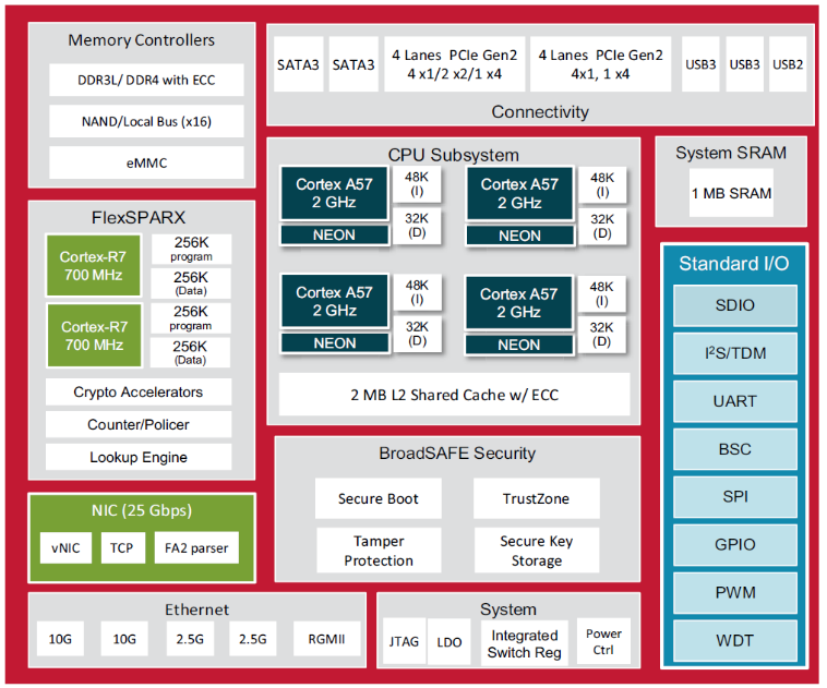
많은 임베디드 SoC 칩은 다양한 기능들을 한 개의 칩에 포함시켜 제공한다. 먼저 SoC H/W 구조 및 기능들을 Boradcom사의 BCM6862X 칩을 예로 알아본다. 이 칩은 최신 arm64를 사용하는 상용 cpu이며, 제공하는 내부 기능은 다음과 같다. (Northstar 2라는 이름을 사용하며 줄여서 ns2이다.)
- ARM Cortex-A57(arm64) 2 Ghz x 4 CPU core
- DDR3 및 DDR4용Memory Controller
- 내장 SRAM 1M
- NAND/NOR Flash Controller
- eMMC Controller
- 버스: SATA 3 x 2, PCIe Gen2 4 lane x 2, USB3 x 2, USB2 x 1
- 네트워크 Controller
- 네트워크 Accelation을 목적으로 사용하는 추가 ARM Cortex R7 700Mhz x 2 core
- 10G x 2, 2.5G x 2, 1G x 1 이더넷 MAC
- Security 목적의 Secure Boot, TrustZone, …
- 그 외 다양한 표준 입출력 장치들
아래 그림은 위의 칩이 가지고 있는 기능들을 블록도로 표현하였다.
주의: Broadcom 사의 데이터 시트에 나오는 정보들 중 이미 어느 정도 알려진 public한 정보들만을 일부 발췌하여 설명하기 위한 자료로 사용한다. 그러나 저작권상 보호를 받는 이미지들이므로 일부를 가려 사용하였고, 이 들을 복사하여 사용하지 않도록 주의해야 한다.
위에서 보여준 그림과 같이 SoC 내부에 있는 다양한 기능들을 SoC 외부에 있는 회로와 연결하기 위해 많은 핀(pin)들이 사용된다. (아래 그림은 특정 칩을 지칭하지 않음)
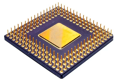
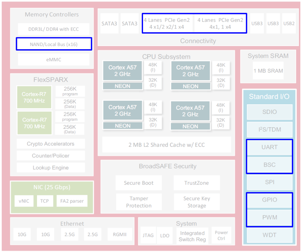
대부분의 임베디드 SoC(System On a Chip)는 수백개의 핀(pin)들을 사용한다. 이 핀들은 한 가지 기능을 위해 사용되는 것들도 있지만, 여러 가지 기능이 한 개의 핀(pin)에 선택적으로 제공되기도 하는데 바로 아래 그림 파란 박스의 기능들이 MFIO(Multi Function I/O) 핀(pin)에 연결된 기능들이다. 업체마다 다양한 표현을 사용한다. (Pin Multiplexing 또는 Pin Mux라고도 한다.)
Pin 디스크립터
아래 그림은 SoC에서 사용하는 핀(pin)들 중 일부(좌측 하단) 1/4 만을 보여준다. 노란색 박스로 되어있는 핀들이 MFIO(Multi Function I/O)에 사용되는 핀들이다. W열의 4번째 위치한 박스가 MFIO16이라는 핀 명칭을 가진 것을 확인할 수 있을 것이다.
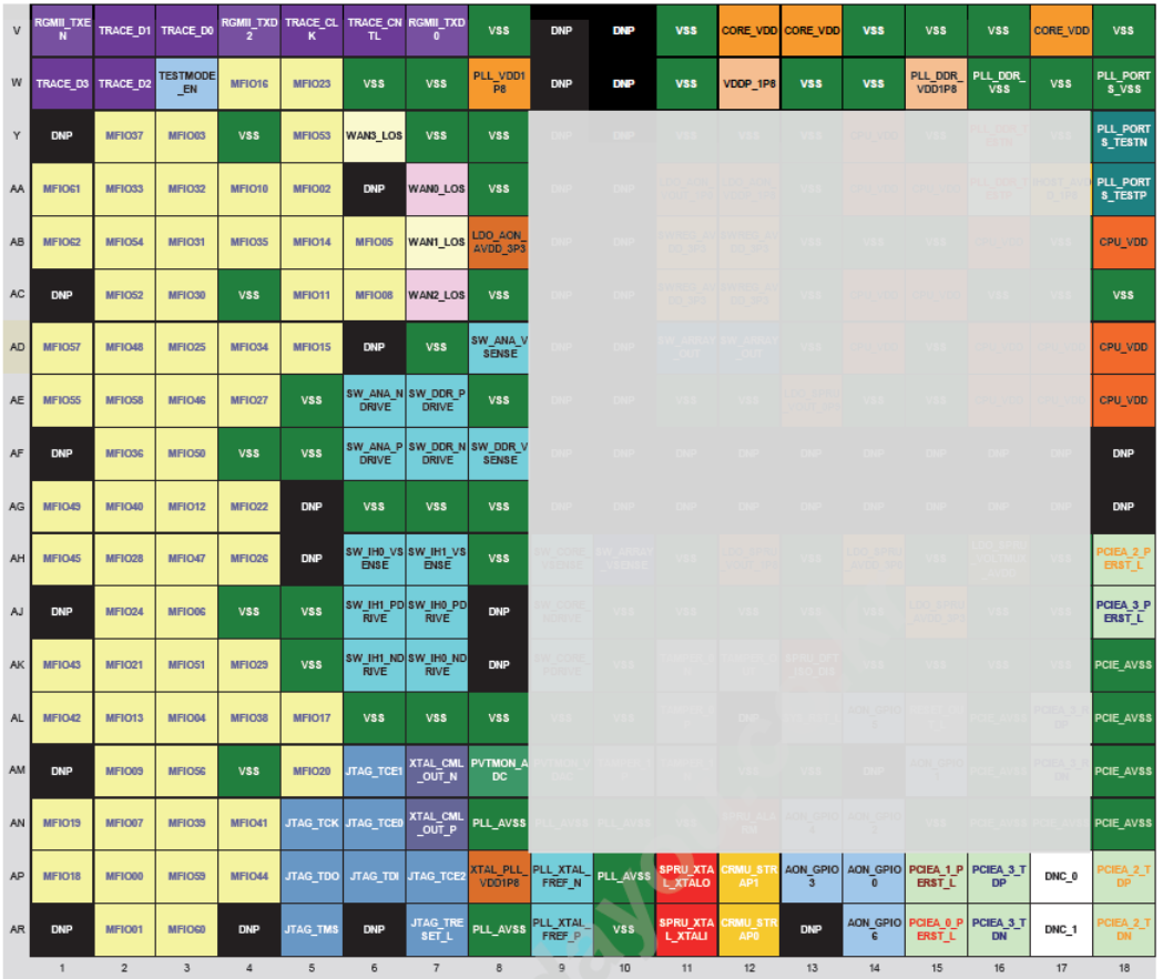
이 칩이 제공하는 MFIO 핀들은 아래 표와 같이 총 63개이다. 아래 표에서 Signal이 각 핀의 이름을 의미하며 Ball은 물리적 핀 배치를 의미한다. 예를 들어 MFIO00 핀은 AP열의 2번째에 위치한다.
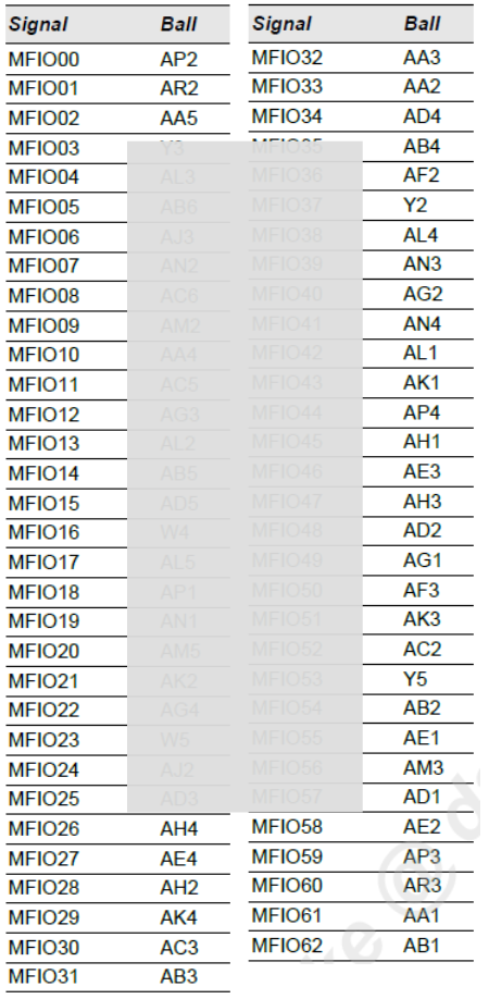
대부분의 pinctrl 드라이버들은 모든 핀에 명칭을 붙여 준비하지 않고, 기능을 선택하여 사용하는 MFIO(Multi Function I/O) 핀에 대해서만 준비하여 사용한다. 벤더들이 pinctrl 드라이버를 제공하기 위해 PIN에 명칭을 부여할 때 다음과 같은 pinctrl_pin_desc 구조체를 사용한다. number에 0번부터 시작하는 순번이 들어가며, name 필드에는 핀 명이 대입된다.
include/linux/pinctrl/pinctrl.h
/**
 * struct pinctrl_pin_desc - boards/machines provide information on their
 * pins, pads or other muxable units in this struct
 * @number: unique pin number from the global pin number space
 * @name: a name for this pin
 * @drv_data: driver-defined per-pin data. pinctrl core does not touch this
 */
struct pinctrl_pin_desc {
        unsigned number;
        const char *name;
        void *drv_data;
};
Generic 사용 예)
핀들이 복수개이므로 구조체를 보통 컴파일 타임에 배열로 생성하는데 이를 편하게 지정하기 위해 PINCTRL_PIN() 매크로를 사용하여 지정한다. 다음 예에서는 pin 명칭에 XY좌표를 사용하여 간단히 주어진 것을 보여준다.
/* Convenience macro to define a single named or anonymous pin descriptor */
#define PINCTRL_PIN(a, b) { .number = a, .name = b

const struct pinctrl_pin_desc foo_pins[] = {
      PINCTRL_PIN(0, "A8"),
      PINCTRL_PIN(1, "B8"),
      ...
      PINCTRL_PIN(63, "H1"),
};
Broadcom rpi2 소스 코드 사용 예
다음 rpi2 드라이버에서 핀 명칭을 지정하는 방식을 알아보자. 핀 명칭을 간단히 gpio0 ~ gpio53까지 부여한 것을 볼 수 있다.
drivers/pinctrl/bcm/pinctrl-bcm2835.c
/* pins are just named GPIO0..GPIO53 */
#define BCM2835_GPIO_PIN(a) PINCTRL_PIN(a, "gpio" #a)
static struct pinctrl_pin_desc bcm2835_gpio_pins[] = {
        BCM2835_GPIO_PIN(0),
        BCM2835_GPIO_PIN(1),
        BCM2835_GPIO_PIN(2),
        ...
        BCM2835_GPIO_PIN(53),
}
Broadcom ns2 소스 코드 사용 예
다음 ns2 드라이버에서 핀 명칭을 약간 변형하여 지정하는 방식을 알아보자. pinctrl_pin_desc 구조체를 직접 사용하거나 PINCTRL_PIN() 매크로를 사용하지 않고, 벤더가 선언한 구조체를 사용하여 그냥 정의한 것을 볼 수 있다. 참고로 일부 벤더들은 PINCTRL_PIN() 매크로를 사용하지 않고, foo_PINCTRL_PIN() 매크로 또는 foo_PIN_DESC() 매크로를 별도로 정의하여 사용하기도한다.
drivers/pinctrl/bcm/pinctrl-ns2-mux.c
/*
 * Description of a pin in Northstar2
 *
 * @pin: pin number
 * @name: pin name
 * @pin_conf: pin configuration structure
 */
struct ns2_pin {
        unsigned int pin;
        char *name;
        struct ns2_pinconf pin_conf;
};

#define NS2_PIN_DESC(p, n, b, o, s, i, pu, d)   \
{                                               \
        .pin = p,                               \
        .name = n,                              \
        .pin_conf = {                           \
                .base = b,                      \
                .offset = o,                    \
                .src_shift = s,                 \
                .input_en = i,                  \
                .pull_shift = pu,               \
                .drive_shift = d,               \
        }                                       \
}

/*
 * List of pins in Northstar2
 */
static struct ns2_pin ns2_pins[] = {
        NS2_PIN_DESC(0, "mfio_0", -1, 0, 0, 0, 0, 0),
        NS2_PIN_DESC(1, "mfio_1", -1, 0, 0, 0, 0, 0),
        NS2_PIN_DESC(2, "mfio_2", -1, 0, 0, 0, 0, 0),
        NS2_PIN_DESC(3, "mfio_3", -1, 0, 0, 0, 0, 0),
        ...
        NS2_PIN_DESC(116, "usb2_overcurrent", 2, 0x38, 7, 6, 3, 0),
        NS2_PIN_DESC(117, "sata_led1", 2, 0x3c, 15, 14, 11, 8),
        NS2_PIN_DESC(118, "sata_led0", 2, 0x3c, 7, 6, 3, 0),
};
NS2_PIN_DESC() 매크로를 보면 pin 디스크립터에 pin configuration(pinconf)에서 사용할 정보까지 담아 놓았음을 확인할 수 있다.
pinctrl_pin_desc 구조체 및 PINCTRL_PIN() 매크로를 사용하지 않고 임시로 구성한 핀 정보들은 probe 시에 호출되는 foo_probe() 함수에서 pinctrl_pin_desc 구조체 배열을 동적으로 할당 한 후 이 곳에 핀 정보를 복사하여 구성하는 방식을 사용한다. 다음 ns2의 probe 함수 예를 확인하자.
drivers/pinctrl/bcm/pinctrl-ns2-mux.c
static int ns2_pinmux_probe(struct platform_device *pdev)
{
        struct ns2_pinctrl *pinctrl;
        struct resource *res;
        int i, ret;
        struct pinctrl_pin_desc *pins;
        unsigned int num_pins = ARRAY_SIZE(ns2_pins);

        pinctrl = devm_kzalloc(&pdev->dev, sizeof(*pinctrl), GFP_KERNEL);
        if (!pinctrl)
                return -ENOMEM;
        ...
        pins = devm_kcalloc(&pdev->dev, num_pins, sizeof(*pins), GFP_KERNEL);
        if (!pins)
                return -ENOMEM;

        for (i = 0; i < num_pins; i++) {
                pins[i].number = ns2_pins[i].pin;
                pins[i].name = ns2_pins[i].name;
                pins[i].drv_data = &ns2_pins[i];
        }
        ...
        pinctrl->pctl = pinctrl_register(&ns2_pinctrl_desc, &pdev->dev, pinctrl);
        ...
PIN 멀티플렉싱 (pinmux)
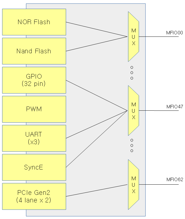
이렇게 여러 가지 기능을 하나의 pin에 제공하면 SoC 설계 시 핀 수를 줄여 핀이 차지하는 공간을 줄일 수 있는 장점이 있다. 사용자는 회로 설계 시 필요한 기능을 골라서 선택하여 사용할 수 있다. 한 개의 핀에 연결된 기능들은 한 가지만을 선택하여 사용하여야 하고 동시에 사용할 수 없는 단점이 있다. 다음 그림을 보면 NOR Flash 기능과 Nand Flash 기능을 사용할 때 각 기능에 대해 많은 핀들이 사용된다. 최근에는 NOR Flash와 Nand Flash를 동시에 제공하지 않고 선택 적용하는 케이스들이 많이 있다. 이러한 시스템에서 핀을 선택하기 위해 사용하는 방법이 PIN 멀티 플렉싱을 사용한다. 아래 MFIO(Multi Function I/O) 0번 핀에 두 가지 기능이 선택될 수 있는 것을 알 수 있다.
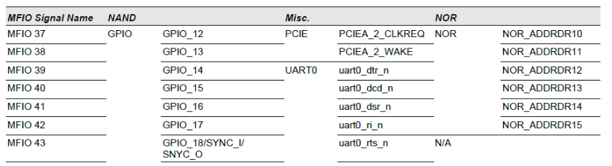
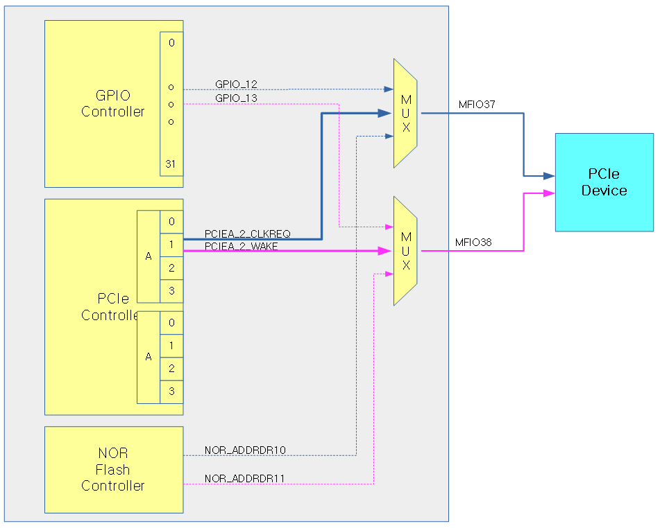
다음 표는 MFIO 각 핀들이 사용할 수 있는 기능들을 보여준다. 예를 들어 MFIO 37번 핀은 3가지의 기능을 사용할 수 있고, 각각 GPIO 12번, PCIE A버스의 2번째 lane 또는 Nor 플래시 중 하나에 사용될 수 있다. 즉 H/W 설계 시 PCIe A버스의 2번째 lane을 사용하여야 하는 경우 GPIO의 12번~13번 핀 및 Nor 플래시 등을 이용할 수 없게됨을 알 수 있다.
다음 그림은 위의 표를 참조하여 MFIO37번 핀에 연결된 3개의 기능들이 연결되어 있는 모습을 보여준다.
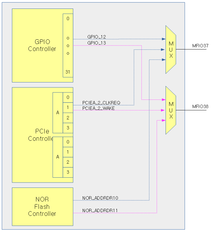
이어서 MFIO37번과 MFIO38번이 PCIe 디바이스에 연결된 모습을 보여준다. 이 경우 GPIO_12번과 GPIO_13번 및 NOR 플래시 디바이스를 연결하여 사용할 수 없다.
pinmux 설정
pinmux를 통해 function을 설정하는 방법은 다음과 같은 방법들이 있다.
SoC 내부 디폴트 설정
MFIO 핀을 어떠한 용도로 사용할지는 SoC가 각 MFIO 핀 별로 부트업시 default 설정이 지정된다. 물론 각 제조사의 칩 데이터 시트를 참고해야 한다
부트 스트랩에 의한 설정
H/W 설계 시 bootstrap 설정에 의해 모드가 지정되는 MFIO 핀들도 있다. 이 경우에는 각 제조사의 데이터 시트를 참고하여 처음 모드가 어떻게 되는지 알아볼 수 있다.
S/W 설정
pin control 드라이버를 통해 커널 부트업시 각 MFIO 핀의 모드를 mux 레지스터의 조작을 통해 설정할 수 있다. 최근 커널은 당연히 디바이스 트리를 읽어서 자동으로 설정한다. 부트 후에도 커널에서는 pinctrl에 대한 kernel API를 사용하여 pinmux 및 pinconf 설정이 가능하다. 또한 유저 스페이스에서도 모드를 바꿀 수 있는 시스템 파일 경로를 제공한다.
- 디바이스 트리를 사용하기 전에는 각 아키텍처로 만들어진 머신(보드)에 대한 초기화 코드에 pinmux 및 pinconf에 대한 설정을 해왔다.
- 디바이스 트리를 사용하면서부터(64비트 디폴트) 디바이스 트리에서 pinmux 및 pinconf에 대한 설정을 할 수 있게 되었다.
Pin Configuration (pinconf)
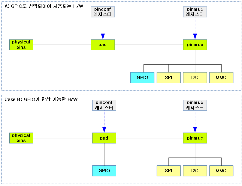
pin configuration은 대부분 GPIO 서브시스템과 같이 사용된다. GPIO를 사용할 때 pinmux로 선택하는지 아니면 항상 동작하는지에 따라 두 가지 유형으로 나뉜다.
- case A)와 같은 경우 GPIO를 사용하려면 pinmux에 선택되어 사용되어야 한다. 대부분의 경우 pinmux에서 GPIO는 디폴트로 선택되어 있다.
- case B)와 같은 경우 GPIO가 항상 동작 가능한 상태이다. 뒷 부분에 있는 pinmux에 의해 특정 장치가 선택되어 사용될 때 동시에 연결되어 사용되고 있는 GPIO가 방해를 하지 않도록 조심해야 한다.
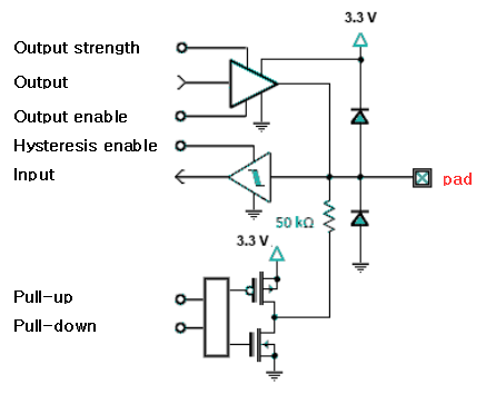
아래 그림은 rpi2의 gpio 핀 하나를 대략적으로 보여준다. 여기에서 pad의 위치를 확인해본다.
- 가장 상위의 삼각형 모습이 pad가 출력 모드로 설정되는 경우 동작하는 회로이다.
- 그다음 삼각형 모습은 pad가 입력 모드로 설정되는 경우 동작하는 회로이다.
- 아래 MOS-FET가 있는 곳은 pad에 pull-up 및 pull-down 바이어스를 연결하기 위한 회로이다.
다음에서 설정할 수 있는 속성들을 알아보자. 물론 H/W마다 지원하는 속성이 있다. 각각의 속성 지원 여부는 칩제조사의 데이터시트를 확인해야한다. 기존 칩 제조사의 pin controller의 확인은 Document/devicetree/binding/pinctrl 디렉토리에서 확인할 수 있다.
출력 관련
- output-low
- 로우 레벨 출력 모드로 설정한다.
- output-high
- 하이 레벨 출력 모드로 설정한다.
- drive-push-pull
- 출력을 push & pull 모드로 설정한다.
- drive-open-drain
- 출력을 open drain 모드로 설정한다.
- drive-open-source
- 출력을 open source 모드로 설정한다.
- drive-strength
- 드라이브 출력을 X mA로 설정한다.
입력 관련
- bias-pull-down
- 입력 핀에 pull-down 바이어스 전류를 공급한다.
- bias-pull-up
- 입력 핀에 pull-up 바이어스 전류를 공급한다.
- bias-high-impedance
- pull-up도 아니고 pull-down도 아닌 중간 high-impedance 상태가 유지되도록 입력 핀에 바이어스를 공급한다.
- bias-bus-hold
- 핀에 입력된 시그널 상태를 기억하여 다음 신호 입력 전까지 기존 상태를 유지한다.
- 래치와 같이 동작하도록 입력 핀에 약한 피드백 전류를 공급하여 상태를 유지하게 한다.
- bias-disable
- 핀에 바이어스 전류를 공급하지 않는다.
- bias-pull-pin-default
- 핀에 디폴트 상태의 바이어스 전류를 공급한다.
- input-enable
- 입력 핀을 enable 한다.
- 출력 모드일 때에는 영향이 없다
- input-schmitt-enable
- schmitt 트리거 모드를 enable한다.
- input-schmitt-disable
- schmitt 트리거 모드를 disable한다.
- input-debounce
- 디바운스 모드로 동작시키고 디바운스 타임 X를 설정한다.
기타
- power-source
- 다른 파워 공급(서플라이)을 선택할 수 있다.
- low-power-enable
- 저 전력 모드를 enable 한다.
- low-power-disable
- 저 전력 모드를 disable 한다.
다음 그림에서 보여주는 바이어스 전류 공급 방법이 가장 많이 사용하는 방법들이다.

Pin Control 드라이버 구조
아래의 그림은 pin control 드라이버와 관련된 구조를 보여준다.
- 우측 파란 박스가 pinctrl 드라이버 구현부분이다.
- Pinctrl 서브시스템 코어는 각 클라이언트 디바이스 드라이버 내부에서 API로 요청하는 pinmux/pinconf 설정을 받아들인다.
- 좌측 아래 회색 박스의 디바이스 트리를 보면 부트업 타임에 pinmux 및 pinconf에 대한 state 매핑을 등록한다.

GPIO 드라이버와의 연계
최근의 SoC는 MFIO와 GPIO 기능이 동시에 제공되므로 이러한 기능을 한 개의 드라이버에서 구현하여 제공하기도 한다.
- 특정 장치들은 pin controller가 사용하는 모든 pin이 gpio와 1:1로 구성되는 경우도 있다. (예: rpi2)
Interrupt Controller 드라이버와의 연계
또한 GPIO 내부에 일부 입력핀들이 외부 인터럽터를 수신할 수 있도록 구성된 Interrupt 멀티플렉서 장치들도 많이 구성된다. 따라서 최근에는 Pin Controller + GPIO Controller + Interrupt Controller가 동시에 제공되는 드라이버를 구성하기도 한다. (예: rpi2, exynos, omap, dra7, am437, sunxi, …)
pinctrl 드라이버를 작성할 때 pinctrl 디스크립터를 통해 3개의 오퍼레이션을 구현하고, 추가로 GPIO Controller 및 Interrupt Controller도 여러 가지 구현 경우에 따라 추가될 수 있음을 알 수 있다.

Pin Controller
pin controller 디바이스 드라이버는 다음과 같이 3개의 오퍼레이션으로 구현된다.
디바이스 드라이버의 pinmux/pinconf 요청
커널 부트업시 디바이스 트리로 구성되어 가동되는 여러 기능의 드라이버들 중 일부가 MFIO핀을 이용하는 경우 pinmux와 같이 자신의 기능을 선택하기위해 요청하는 기능이 있다. 또한 핀의 모드를 설정하기 위해 pinconf 요청을 할 수도 있다.
pinctrl 디스크립터
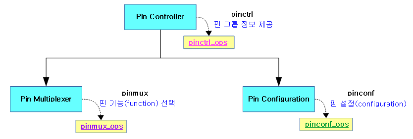
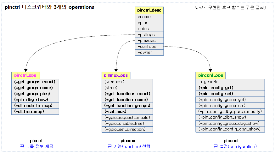
pinctrl 디스크립터의 정의는 다음과 같이 pinctrl_desc 구조체를 사용하여 정의된다. pin 디스크립터에서 정의한 pin들을 지정하고 있고, 이 핀들을 대상으로 pinctrl 서브시스템용 API가 구현될 수 있도록 3가지의 operation 구조체 후크를 사용한다. 3가지의 오퍼레이션은 다음의 기능을 지원한다.
- pinctrl_ops
- 핀 그룹에 소속된 핀들 정보를 제공한다.
- pinmux_ops
- 핀에 연결된 기능을 선택한다.
- pinconf_ops
- 핀의 속성(pull up, pull down, open drain, strength, …)을 설정한다.
다음 그림은 pinctrl 디스크립터와 구현해야 할 3개의 오퍼레이션들을 보여준다.
첫 번째 예) rpi2 드라이버
drivers/pinctrl/bcm/pinctrl-bcm2835.c
static struct pinctrl_desc bcm2835_pinctrl_desc = {
        .name = MODULE_NAME,
        .pins = bcm2835_gpio_pins,
        .npins = ARRAY_SIZE(bcm2835_gpio_pins),
        .pctlops = &bcm2835_pctl_ops,
        .pmxops = &bcm2835_pmx_ops,
        .confops = &bcm2835_pinconf_ops,
        .owner = THIS_MODULE,
};
두 번째 예) ns2 드라이버 – pins 필드는 probe 함수에서 동적으로 생성되는 pin 디스크립터 정보들을 대입하므로 컴파일 타임에 지정하지 않는다.
drivers/pinctrl/bcm/pinctrl-ns2-mux.c
static struct pinctrl_desc ns2_pinctrl_desc = {
        .name = "ns2-pinmux",
        .pctlops = &ns2_pinctrl_ops,
        .pmxops = &ns2_pinmux_ops,
        .confops = &ns2_pinconf_ops,
};
1) Pin 그룹 (for pinctrl & pinconf)
pin control을 사용하는 기능들은 1개 이상의 핀들을 사용한다. 각 기능들이 사용하는 MFIO 핀들을 알아본다. 다음 그림에서 8 개의 핀에 대한 그룹 분류를 알아보자.
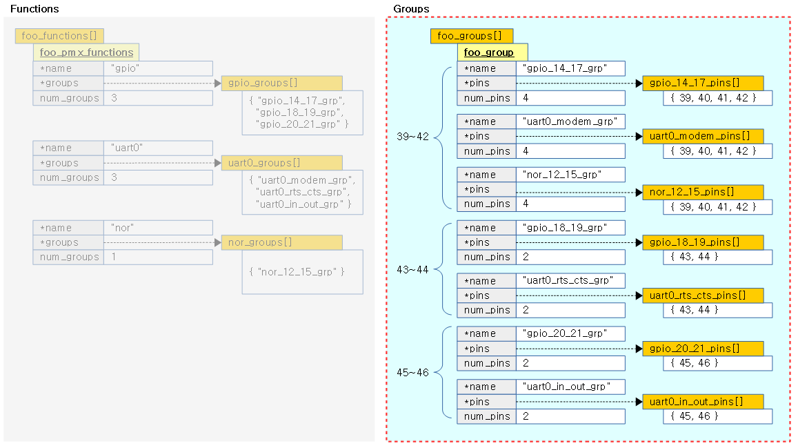
Generic 사용 예
예를 들어 UART0를 사용하기 위해서 MFIO_39 ~ MFIO_46번까지 8개의 핀이 사용되고, 이를 용도별로 3개의 그룹으로 나누어 표현하면 다음과 같다.
static const unsigned int uart0_modem_pins[] = {39, 40, 41, 42};
static const unsigned int uart0_rts_cts_pins[] = {43, 44};
static const unsigned int uart0_in_out_pins[] = {45, 46};
GPIO는 MFIO_24 ~ MFIO_25, MFIO_27 ~ MFIO_56번까지의 32개의 핀이 사용되는데, UART0와 중복되어 사용되는 핀들의 그룹을 정리하면 다음과 같다.
static const unsigned int gpio_14_17_pins[] = {39, 40, 41, 42};
static const unsigned int gpio_18_19_pins[] = {43, 44};
static const unsigned int gpio_20_21_pins[] = {45, 46};
마지막으로 NOR 플래시는 MFIO_0 ~ MFIO_42번까지 43개의 핀이 사용되는데, UART0와 중복되어 사용되는 핀 그룹은 다음과 같다.
static const unsigned int nor_addr_12_15_pins[] = {39, 40, 41, 42};
핀 그룹들을 관리하는 방법들은 드라이버 개발자마다 조금씩 다르게 구현하지만 기본 형태는 다음과 같다. 다음 코드에서 8개의 MFIO_39 ~ MFIO_46 핀들에 대한 그룹들의 분류를 알아본다.
#include <linux/pinctrl/pinctrl.h>
struct foo_group {
	const char *name;
	const unsigned int *pins;
	const unsigned num_pins;
};

static const struct foo_group foo_groups[] = {
        ...
	{
		.name = "gpio_14_17_grp",
		.pins = gpio_14_17_pins,
		.num_pins = ARRAY_SIZE(gpio_14_17_pins),
	},
	{
		.name = "uart0_modem_grp",
		.pins = uart0_modem_pins,
		.num_pins = ARRAY_SIZE(uart0_modem_pins),
	},
        {
                .name = "nor_addr_12_15_grp",
                .pins = nor_addr_12_15_pins,
                .num_pins = ARRAY_SIZE(nor_addr_12_15_pins),
        },
	{
		.name = "gpio_18_19_grp",
		.pins = gpio_18_19_pins,
		.num_pins = ARRAY_SIZE(gpio_18_19_pins),
	},
	{
		.name = "uart0_rts_cts_grp",
		.pins = uart0_rts_cts_pins,
		.num_pins = ARRAY_SIZE(uart0_rts_cts_pins),
	},
	{
		.name = "gpio_20_21_grp",
		.pins = gpio_20_21_pins,
		.num_pins = ARRAY_SIZE(gpio_20_21_pins),
	},
	{
		.name = "uart0_in_out_grp",
		.pins = uart0_in_out_pins,
		.num_pins = ARRAY_SIZE(uart0_in_out_pins),
	},

        ...
};
Broadcom ns2 소스 코드 사용 예
다음은 8개의 MFIO_39_46 핀들에 대한 broadcom ns2의 실제 소스 코드이다.
drivers/pinctrl/bcm/pinctrl-ns2-mux.c
/*
 * Group based IOMUX configuration
 *
 * @name: name of the group
 * @pins: array of pins used by this group
 * @num_pins: total number of pins used by this group
 * @mux: Northstar2 group based IOMUX configuration
 */
struct ns2_pin_group {
        const char *name;
        const unsigned int *pins;
        const unsigned int num_pins;
        const struct ns2_mux mux;
};
generic한 foo_group 구조체 형태에서 ns2_mux 구조체가 하나 더 추가되었다.
/*
 * Northstar2 IOMUX register description
 *
 * @base: base address number
 * @offset: register offset for mux configuration of a group
 * @shift: bit shift for mux configuration of a group
 * @mask: mask bits
 * @alt: alternate function to set to
 */
struct ns2_mux {
        unsigned int base;
        unsigned int offset;
        unsigned int shift;
        unsigned int mask;
        unsigned int alt;
};
generic foo_group 구조체 형태에 function을 선택하기 위한 Mux 레지스터 주소 및 컨트롤 정보등을 추가하기 위해 ns2_mux 구조체를 사용하였다.
#define NS2_PIN_GROUP(group_name, ba, off, sh, ma, al)  \
{                                                       \
        .name = __stringify(group_name) "_grp",         \
        .pins = group_name ## _pins,                    \
        .num_pins = ARRAY_SIZE(group_name ## _pins),    \
        .mux = {                                        \
                .base = ba,                             \
                .offset = off,                          \
                .shift = sh,                            \
                .mask = ma,                             \
                .alt = al,                              \
        }                                               \
}


/*
 * List of Northstar2 pin groups
 */
static const struct ns2_pin_group ns2_pin_groups[] = {
	...
        NS2_PIN_GROUP(gpio_14_17, 0, 4, 18, 3, 0),
        NS2_PIN_GROUP(uart0_modem, 0, 4, 18, 3, 1),
        NS2_PIN_GROUP(nor_addr_12_15, 0, 4, 18, 3, 2),

        NS2_PIN_GROUP(gpio_18_19, 0, 4, 16, 3, 0),
        NS2_PIN_GROUP(uart0_rts_cts, 0, 4, 16, 3, 1),

        NS2_PIN_GROUP(gpio_20_21, 0, 4, 14, 3, 0),
        NS2_PIN_GROUP(uart0_in_out, 0, 4, 14, 3, 1),
	...
};
generic foo_groups[] 배열 을 구성하는데 <name>_grp, <name>_pins, 핀 수 및 mux 정보(base, offset, shift, mask, alt) 등을 컴파일 타임에 정의한다.
Pin 그룹 오퍼레이션 구현
정의된 핀 그룹에 대한 조회등을 할 수 있는 pinctrl 오퍼레이션을 구현하는 방법을 알아보자.
Generic 사용 예
static int foo_get_groups_count(struct pinctrl_dev *pctldev)
{
	return ARRAY_SIZE(foo_groups);
}

static const char *foo_get_group_name(struct pinctrl_dev *pctldev,
				       unsigned selector)
{
	return foo_groups[selector].name;
}

static int foo_get_group_pins(struct pinctrl_dev *pctldev, unsigned selector,
			       const unsigned **pins,
			       unsigned *num_pins)
{
	*pins = (unsigned *) foo_groups[selector].pins;
	*num_pins = foo_groups[selector].num_pins;
	return 0;
}

static struct pinctrl_ops foo_pctrl_ops = {
	.get_groups_count = foo_get_groups_count,
	.get_group_name = foo_get_group_name,
	.get_group_pins = foo_get_group_pins,
};

static struct pinctrl_desc foo_desc = {
       ...
       .pctlops = &foo_pctrl_ops,
};
핀 디스크립터에는 3가지의 operations가 지정되는데 첫 번째로 핀 컨트롤러의 핀 그룹 정보를 담당하는 pctlops에 해당하는 operation에 다음 3개의 함수를 구현한다.
- (*get_groups_count)
- 등록된 그룹들의 수를 반환한다.
- (*get_group_name)
- selector를 인덱스로 그룹명을 반환한다.
- (*get_group_pins)
- selector를 인덱스로 그룹을 찾아 출력 인수 pins에 핀 목록. 그리고 출력 인수 num_pins에 핀 수를 반환한다.
- 예) selector=0 (gpio_pin_14_17을 찾은 것으로 하자)
- -> pin={ 14, 15, 16, 17 }, num_pins=4
Broadcom ns2 소스 코드 사용 예
다음 코드는 broadcom ns2의 실제 소스 코드이다.
drivers/pinctrl/bcm/pinctrl-ns2-mux.c
static int ns2_get_groups_count(struct pinctrl_dev *pctrl_dev)
{
        struct ns2_pinctrl *pinctrl = pinctrl_dev_get_drvdata(pctrl_dev);

        return pinctrl->num_groups;
}

static const char *ns2_get_group_name(struct pinctrl_dev *pctrl_dev,
                                      unsigned int selector)
{
        struct ns2_pinctrl *pinctrl = pinctrl_dev_get_drvdata(pctrl_dev);

        return pinctrl->groups[selector].name;
}

static int ns2_get_group_pins(struct pinctrl_dev *pctrl_dev,
                              unsigned int selector, const unsigned int **pins,
                              unsigned int *num_pins)
{
        struct ns2_pinctrl *pinctrl = pinctrl_dev_get_drvdata(pctrl_dev);

        *pins = pinctrl->groups[selector].pins;
        *num_pins = pinctrl->groups[selector].num_pins;

        return 0;
}

static void ns2_pin_dbg_show(struct pinctrl_dev *pctrl_dev,
                             struct seq_file *s, unsigned int offset)
{
        seq_printf(s, " %s", dev_name(pctrl_dev->dev));
}

static const struct pinctrl_ops ns2_pinctrl_ops = {
        .get_groups_count = ns2_get_groups_count,
        .get_group_name = ns2_get_group_name,
        .get_group_pins = ns2_get_group_pins,
        .pin_dbg_show = ns2_pin_dbg_show,
        .dt_node_to_map = pinconf_generic_dt_node_to_map_pin,
        .dt_free_map = pinctrl_utils_free_map,
};

static struct pinctrl_desc ns2_pinctrl_desc = {
        .name = "ns2-pinmux",
        .pctlops = &ns2_pinctrl_ops,
        ...
};
generic 사용 예보다 3개의 함수가 추가로 구현되어 있음을 알 수 있다.
- (*pin_dbg_show)
- debugfs(CONFIG_DEBUG_FS 커널 옵션 사용)를 사용하는 경우 pin control subsystem core를 통하여 pin 정보를 출력할 수 있다.
- 예) $ cat /sys/kernel/debug/pins
- 호출 경로:
- &pinctrl_pins_ops.(*open) ->
- pinctrl_pins_open() ->
- single_open(file, pinctrl_pins_show, …) ->
- pinctrl_pins_show() ->
- pctldev->desc->pctlops->(*pin_dbg_show)
- (*dt_node_to_map)
- 디바이스 트리를 통해서 그룹에 pinmux, 또는 핀/그룹에 pinconf 설정을 하도록 매핑한다.
- 호출 경로:
- pinctrl_register() ->
- pinctrl_get() ->
- create_pinctrl() ->
- pinctrl_dt_to_map() ->
- dt_to_map_one_config() ->
- pctldev->desc->pctlops->(*dt_node_to_map)
- (*dt_free_map)
- 디바이스 트리를 통해서 매핑한 설정을 해제한다.
- 호출 경로:
- pinctrl_unregister() ->
- pinctrl_put() ->
- pinctrl_release() ->
- pinctrl_free() ->
- pinctrl_dt_free_maps() ->
- dt_free_map() ->
- dt_to_map_one_config() ->
- pctldev->desc->pctlops->(*dt_node_to_map)
2) Pin Function (for pinmux)
그룹화된 핀들을 기능(Function)으로 묶는 것을 알아본다.
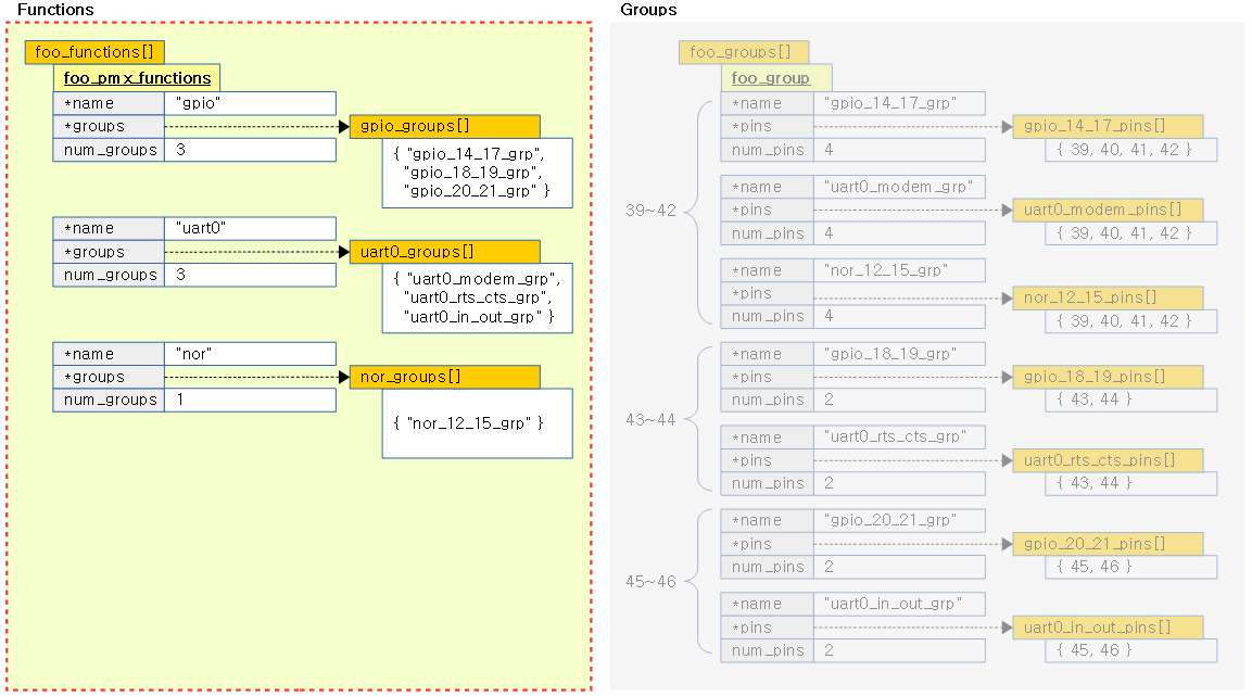
Generic 사용 예
예를 들어 UART0를 사용하기 위해서는 uart0_modem_grp, uart0_rts_cts_grp, uart0_in_out_grp이 필요하다. 다음 코드 예를 보고 uar0_groups가 어떻게 구성이 되었는지 확인해본다.
static const char * const gpio_groups[] = { "gpio_14_17_grp", "gpio_18_19_grp", "gpio_20_21_grp" };
static const char * const uart0_groups[] = { "uart0_modem_grp", "uart0_rts_cts_grp", "uart0_in_out_grp" };
static const char * const nor_groups[] = { "nor_addr_12_15_grp" };

static const struct foo_pmx_func foo_functions[] = {
        ...
	{
		.name = "gpio",
		.groups = gpio_groups,
		.num_groups = ARRAY_SIZE(gpio_groups),
	},
	{
		.name = "uart0",
		.groups = uart0_groups,
		.num_groups = ARRAY_SIZE(uart0_groups),
	},
	{
		.name = "nor",
		.groups = nor_groups,
		.num_groups = ARRAY_SIZE(nor_groups),
	},
        ...
};
Broadcom ns2 소스 코드 사용 예
다음 코드는 broadcom ns2의 실제 코드이다.
drivers/pinctrl/bcm/pinctrl-ns2-mux.c
/*
 * List of groups supported by functions
 */

static const char * const nand_grps[] = {"nand_grp"};

static const char * const nor_grps[] = {"nor_data_grp", "nor_adv_grp",
        "nor_addr_0_3_grp", "nor_addr_4_5_grp", "nor_addr_6_7_grp",
        "nor_addr_8_9_grp", "nor_addr_10_11_grp", "nor_addr_12_15_grp"};

static const char * const gpio_grps[] = {"gpio_0_1_grp", "gpio_2_5_grp",
        "gpio_6_7_grp", "gpio_8_9_grp", "gpio_10_11_grp", "gpio_12_13_grp",
        "gpio_14_17_grp", "gpio_18_19_grp", "gpio_20_21_grp", "gpio_22_23_grp",
        "gpio_24_25_grp", "gpio_26_27_grp", "gpio_28_29_grp",
        "gpio_30_31_grp"};

static const char * const pcie_grps[] = {"pcie_ab1_clk_wak_grp",
        "pcie_a3_clk_wak_grp", "pcie_b3_clk_wak_grp", "pcie_b2_clk_wak_grp",
        "pcie_a2_clk_wak_grp"};

static const char * const uart0_grps[] = {"uart0_modem_grp",
        "uart0_rts_cts_grp", "uart0_in_out_grp"};

static const char * const uart1_grps[] = {"uart1_ext_clk_grp",
        "uart1_dcd_dsr_grp", "uart1_ri_dtr_grp", "uart1_rts_cts_grp",
        "uart1_in_out_grp"};

static const char * const uart2_grps[] = {"uart2_rts_cts_grp"};

static const char * const pwm_grps[] = {"pwm_0_grp", "pwm_1_grp",
        "pwm_2_grp", "pwm_3_grp"};

#define NS2_PIN_FUNCTION(func)                          \
{                                                       \
        .name = #func,                                  \
        .groups = func ## _grps,                        \
        .num_groups = ARRAY_SIZE(func ## _grps),        \
}

/*
 * List of supported functions
 */
static const struct ns2_pin_function ns2_pin_functions[] = {
        NS2_PIN_FUNCTION(nand),
        NS2_PIN_FUNCTION(nor),
        NS2_PIN_FUNCTION(gpio),
        NS2_PIN_FUNCTION(pcie),
        NS2_PIN_FUNCTION(uart0),
        NS2_PIN_FUNCTION(uart1),
        NS2_PIN_FUNCTION(uart2),
        NS2_PIN_FUNCTION(pwm),
};
Pin Mux 오퍼레이션 구현
Generic 사용 예
정의된 핀 Mux에 대한 오퍼레이션을 구현하는 방법은 다음과 같다.
static int foo_get_functions_count(struct pinctrl_dev *pctldev)
{
	return ARRAY_SIZE(foo_functions);
}

static const char *foo_get_fname(struct pinctrl_dev *pctldev, unsigned selector)
{
	return foo_functions[selector].name;
}

static int foo_get_groups(struct pinctrl_dev *pctldev, unsigned selector,
			  const char * const **groups,
			  unsigned * const num_groups)
{
	*groups = foo_functions[selector].groups;
	*num_groups = foo_functions[selector].num_groups;
	return 0;
}

static int foo_set_mux(struct pinctrl_dev *pctldev, unsigned selector,
		unsigned group)
{
	u8 regbit = (1 << selector + group);

	writeb((readb(MUX)|regbit), MUX)
	return 0;
}

static struct pinmux_ops foo_pmxops = {
	.get_functions_count = foo_get_functions_count,
	.get_function_name = foo_get_fname,
	.get_function_groups = foo_get_groups,
	.set_mux = foo_set_mux,
	.strict = true,
};

/* Pinmux operations are handled by some pin controller */
static struct pinctrl_desc foo_desc = {
	...
	.pctlops = &foo_pctrl_ops,
	.pmxops = &foo_pmxops,
};
pinmux를 동작시키는데 필요한 pinmux_ops 구조체에 사용하는 다음 함수들을 구현한다.
- (*get_functions_count)
- 등록된 펑션들의 수를 반환한다.
- (*get_function_name)
- selector를 인덱스로 펑션명을 반환한다.
- (*get_function_groups)
- selector를 인덱스로 펑션을 찾아 해당 펑션에 속한 그룹들 목록을 출력 인수 groups에 대입한다. 그리고 그리고 출력 인수 num_groups에는 그룹 수를 반환한다.
- 예) selector=4 (uart0 펑션을 찾은 것으로 하자)
- -> groups={ “uart0_modem_grp”, “uart0_rts_cts_grp”, “uart0_in_out_grp” }, num_groups=3
- (*set_mux)
- selector를 인덱스로 펑션을 찾고 지정한 그룹을 선택한다.
- 예) selector=4 (uart0 펑션을 찾은 것으로 하자), group=1
- -> pinmux 레지스터를 사용하여 “uart0” 펑션에 소속한 “uart0_rts_cts_grp” 핀들을 선택하게 한다.
Broadcom ns2 소스 코드 사용 예
다음 코드는 broadcom ns2의 실제 소스 코드이다.
drivers/pinctrl/bcm/pinctrl-ns2-mux.c
static int ns2_get_functions_count(struct pinctrl_dev *pctrl_dev)
{
        struct ns2_pinctrl *pinctrl = pinctrl_dev_get_drvdata(pctrl_dev);

        return pinctrl->num_functions;
}

static const char *ns2_get_function_name(struct pinctrl_dev *pctrl_dev,
                                         unsigned int selector)
{
        struct ns2_pinctrl *pinctrl = pinctrl_dev_get_drvdata(pctrl_dev);

        return pinctrl->functions[selector].name;
}

static int ns2_get_function_groups(struct pinctrl_dev *pctrl_dev,
                                   unsigned int selector,
                                   const char * const **groups,
                                   unsigned int * const num_groups)
{
        struct ns2_pinctrl *pinctrl = pinctrl_dev_get_drvdata(pctrl_dev);

        *groups = pinctrl->functions[selector].groups;
        *num_groups = pinctrl->functions[selector].num_groups;

        return 0;
}

static int ns2_pinmux_enable(struct pinctrl_dev *pctrl_dev,
                             unsigned int func_select, unsigned int grp_select)
{
        struct ns2_pinctrl *pinctrl = pinctrl_dev_get_drvdata(pctrl_dev);
        const struct ns2_pin_function *func;
        const struct ns2_pin_group *grp;

        if (grp_select > pinctrl->num_groups ||
                func_select > pinctrl->num_functions)
                return -EINVAL;

        func = &pinctrl->functions[func_select];
        grp = &pinctrl->groups[grp_select];

        dev_dbg(pctrl_dev->dev, "func:%u name:%s grp:%u name:%s\n",
                func_select, func->name, grp_select, grp->name);

        dev_dbg(pctrl_dev->dev, "offset:0x%08x shift:%u alt:%u\n",
                grp->mux.offset, grp->mux.shift, grp->mux.alt);

        return ns2_pinmux_set(pinctrl, func, grp, pinctrl->mux_log);
}

static const struct pinmux_ops ns2_pinmux_ops = {
        .get_functions_count = ns2_get_functions_count,
        .get_function_name = ns2_get_function_name,
        .get_function_groups = ns2_get_function_groups,
        .set_mux = ns2_pinmux_enable,
};

static struct pinctrl_desc ns2_pinctrl_desc = {
        .name = "ns2-pinmux",
        .pmxops = &ns2_pinmux_ops,
        ...
};
generic 코드 예와 거의 동일하다.
다음 아래 코드에 있는 함수는 ns2_pinmux_enable() 함수에서 호출하여 사용하는 함수로 실제 broadcom ns2의 pin controller(MFIO 레지스터)를 이용하여 pin에 대한 function을 설정한다.
drivers/pinctrl/bcm/pinctrl-ns2-mux.c
static int ns2_pinmux_set(struct ns2_pinctrl *pinctrl,
                          const struct ns2_pin_function *func,
                          const struct ns2_pin_group *grp,
                          struct ns2_mux_log *mux_log)
{
        const struct ns2_mux *mux = &grp->mux;
        int i;
        u32 val, mask;
        unsigned long flags;
        void __iomem *base_address;

        for (i = 0; i < NS2_NUM_IOMUX; i++) {
                if ((mux->shift != mux_log[i].mux.shift) ||
                        (mux->base != mux_log[i].mux.base) ||
                        (mux->offset != mux_log[i].mux.offset))
                        continue;

                /* if this is a new configuration, just do it! */
                if (!mux_log[i].is_configured)
                        break;

                /*
                 * IOMUX has been configured previously and one is trying to
                 * configure it to a different function
                 */
                if (mux_log[i].mux.alt != mux->alt) {
                        dev_err(pinctrl->dev,
                                "double configuration error detected!\n");
                        dev_err(pinctrl->dev, "func:%s grp:%s\n",
                                func->name, grp->name);
                        return -EINVAL;
                }

                return 0;
        }
        if (i == NS2_NUM_IOMUX)
                return -EINVAL;

        mask = mux->mask;
        mux_log[i].mux.alt = mux->alt;
        mux_log[i].is_configured = true;

        switch (mux->base) {
        case NS2_PIN_MUX_BASE0:
                base_address = pinctrl->base0;
                break;

        case NS2_PIN_MUX_BASE1:
                base_address = pinctrl->base1;
                break;

        default:
                return -EINVAL;
        }

        spin_lock_irqsave(&pinctrl->lock, flags);
        val = readl(base_address + grp->mux.offset);
        val &= ~(mask << grp->mux.shift);
        val |= grp->mux.alt << grp->mux.shift;
        writel(val, (base_address + grp->mux.offset));
        spin_unlock_irqrestore(&pinctrl->lock, flags);

        return 0;
}
ns2의 pinmux 레지스터를 사용하여 요청한 펑션 인덱스와 그룹 인덱스에 해당하는 핀에 대해 선택하게 한다. (소스 설명 생략)
3) Pin Configuration (for pinconf)
Pin Configuration 오퍼레이션 구현
핀 또는 핀 그룹에 대한 설정을 하거나 조회할 수 있도록 pinconf 오퍼레이션의 구현에 대해 알아본다.
Generic 사용 예
#include <linux/pinctrl/pinctrl.h>
#include <linux/pinctrl/pinconf.h>
#include "platform_x_pindefs.h"

static int foo_pin_config_get(struct pinctrl_dev *pctldev,
		    unsigned offset,
		    unsigned long *config)
{
	struct my_conftype conf;

	... Find setting for pin @ offset ...

	*config = (unsigned long) conf;
}

static int foo_pin_config_set(struct pinctrl_dev *pctldev,
		    unsigned offset,
		    unsigned long config)
{
	struct my_conftype *conf = (struct my_conftype *) config;

	switch (conf) {
		case PLATFORM_X_PULL_UP:
		...
		}
	}
}

static int foo_pin_config_group_get (struct pinctrl_dev *pctldev,
		    unsigned selector,
		    unsigned long *config)
{
	...
}

static int foo_pin_config_group_set (struct pinctrl_dev *pctldev,
		    unsigned selector,
		    unsigned long config)
{
	...
}

static struct pinconf_ops foo_pconf_ops = {
	.pin_config_get = foo_pin_config_get,
	.pin_config_set = foo_pin_config_set,
	.pin_config_group_get = foo_pin_config_group_get,
	.pin_config_group_set = foo_pin_config_group_set,
};

/* Pin config operations are handled by some pin controller */
static struct pinctrl_desc foo_desc = {
	...
	.confops = &foo_pconf_ops,
};
pinconf를 동작시키는데 필요한 pinconf_ops 구조체에 사용하는 다음 함수들을 구현한다.
- (*pin_config_get)
- 핀에 인자로 지정한 pinconf 설정이 있는 경우 그 값을 알아온다.
- (*pin_config_set)
- 핀에 pinconf 설정을 한다.
- (*pin_config_group_get)
- 그룹에 등록된 pinconf 설정이 있는 경우 그 값을 알아온다.
- (*pin_config_group_set)
- 그룹에 속한 핀들에 pinconf 설정을 한다.
Broadcom ns2 소스 코드 사용 예
다음 코드는 broadcom ns2의 실제 코드이다. 현재 그룹에 대한 구현은 보이지 않고 핀에 대한 구현만 있음을 알 수 있다.
drivers/pinctrl/bcm/pinctrl-ns2-mux.c
static int ns2_pin_config_get(struct pinctrl_dev *pctldev, unsigned int pin,
                              unsigned long *config)
{
        struct ns2_pin *pin_data = pctldev->desc->pins[pin].drv_data;
        enum pin_config_param param = pinconf_to_config_param(*config);
        bool pull_up, pull_down;
        u16 arg = 0;
        int ret;

        if (pin_data->pin_conf.base == -1)
                return -ENOTSUPP;

        switch (param) {
        case PIN_CONFIG_BIAS_DISABLE:
                ns2_pin_get_pull(pctldev, pin, &pull_up, &pull_down);
                if ((pull_up == false) && (pull_down == false))
                        return 0;
                else
                        return -EINVAL;

        case PIN_CONFIG_BIAS_PULL_UP:
             ...

        case PIN_CONFIG_BIAS_PULL_DOWN:
             ...

        case PIN_CONFIG_DRIVE_STRENGTH:
             ...

        case PIN_CONFIG_SLEW_RATE:
             ...

        case PIN_CONFIG_INPUT_ENABLE:
             ...

        default:
                return -ENOTSUPP;
        }
}

static int ns2_pin_config_set(struct pinctrl_dev *pctrldev, unsigned int pin,
                              unsigned long *configs, unsigned int num_configs)
{
        struct ns2_pin *pin_data = pctrldev->desc->pins[pin].drv_data;
        enum pin_config_param param;
        unsigned int i;
        u16 arg;
        int ret = -ENOTSUPP;

        if (pin_data->pin_conf.base == -1)
                return -ENOTSUPP;

        for (i = 0; i < num_configs; i++) {
                param = pinconf_to_config_param(configs[i]);
                arg = pinconf_to_config_argument(configs[i]);

                switch (param) {
                case PIN_CONFIG_BIAS_DISABLE:
                        ret = ns2_pin_set_pull(pctrldev, pin, false, false);
                        if (ret < 0)
                                goto out;
                        break;

                case PIN_CONFIG_BIAS_PULL_UP:
                     ...

                case PIN_CONFIG_BIAS_PULL_DOWN:
                     ...

                case PIN_CONFIG_DRIVE_STRENGTH:
                     ...

                case PIN_CONFIG_SLEW_RATE:
                     ...

                case PIN_CONFIG_INPUT_ENABLE:
                     ...

                default:
                        dev_err(pctrldev->dev, "invalid configuration\n");
                        return -ENOTSUPP;
                }
        }
out:
        return ret;
}

static const struct pinconf_ops ns2_pinconf_ops = {
        .is_generic = true,
        .pin_config_get = ns2_pin_config_get,
        .pin_config_set = ns2_pin_config_set,
};

static struct pinctrl_desc ns2_pinctrl_desc = {
        .name = "ns2-pinmux",
        .confops = &ns2_pinconf_ops,
        ...
};
위 코드의 ns2_pin_config_get() 함수에서 PIN_CONFIG_BIAS_DISABLE 항목이 설정되었는지를 알아보기 위해 pull 상태가 모두 다운인 경우에 한해서만 성공(0)을 반환함을 알 수 있다. 핀에 대해 상태를 알아오기 위해 다음의 명령에 따른 함수 호출 경로를 알아본다.
$ cat /sys/kernel/debug/pinctrl/pinconf-pins
- &pinconf_pins_ops 파일 오퍼레이션의 (*open) 후크에 등록된 함수 호출 ->
- pinconf_pins_open() ->
- single_open()을 통해 pinconf_pins_show() 호출 ->
- 등록된 핀 수만큼 루프
- pinconf_dump_pin() 호출 ->
- pinconf_pins_show() ->
- pinconf_generic_dump_pins() ->
- pinconf_generic_dump_one() ->
- 설정 항목 만큼 루프(PIN_CONFIG_BIAS_BUS_HOLD(0) 부터 ~ PIN_CONFIG_SLEW_RATE 까지)
- pin_config_get_for_pin() ->
- pinconf_ops 오퍼레이션의 (*pin_config_get) 호크에 등록된 함수 호출 ->
- ns2의 경우: ns2_pin_config_get()
ns2의 경우 실제 사용할 수 있는 pinconf 항목들은 다음과 같다.
- bias-pull-disable
- bias-pull-up
- bias-pull-down
- drive-strength
- slew-rate
- input-enable
다음 아래 코드에 있는 함수는 ns2_pin_config_get() 및 ns2_pin_config_set() 함수에서 호출하여 사용하는 함수로 실제 broadcom ns2의 pin controller(MFIO 레지스터)를 이용하여 pin에 대한 pull 상태를 확인하거나 pull 상태를 설정한다.
drivers/pinctrl/bcm/pinctrl-ns2-mux.c
static void ns2_pin_get_pull(struct pinctrl_dev *pctrldev,
                             unsigned int pin, bool *pull_up,
                             bool *pull_down)
{
        struct ns2_pinctrl *pinctrl = pinctrl_dev_get_drvdata(pctrldev);
        struct ns2_pin *pin_data = pctrldev->desc->pins[pin].drv_data;
        unsigned long flags;
        u32 val;

        spin_lock_irqsave(&pinctrl->lock, flags);
        val = readl(pinctrl->pinconf_base + pin_data->pin_conf.offset);
        val = (val >> pin_data->pin_conf.pull_shift) & NS2_PIN_PULL_MASK;
        *pull_up = false;
        *pull_down = false;

        if (val == NS2_PIN_PULL_UP)
                *pull_up = true;

        if (val == NS2_PIN_PULL_DOWN)
                *pull_down = true;
        spin_unlock_irqrestore(&pinctrl->lock, flags);
}


static int ns2_pin_set_pull(struct pinctrl_dev *pctrldev, unsigned int pin,
                            bool pull_up, bool pull_down)
{
        struct ns2_pinctrl *pinctrl = pinctrl_dev_get_drvdata(pctrldev);
        struct ns2_pin *pin_data = pctrldev->desc->pins[pin].drv_data;
        unsigned long flags;
        u32 val;
        void __iomem *base_address;

        base_address = pinctrl->pinconf_base;
        spin_lock_irqsave(&pinctrl->lock, flags);
        val = readl(base_address + pin_data->pin_conf.offset);
        val &= ~(NS2_PIN_PULL_MASK << pin_data->pin_conf.pull_shift);

        if (pull_up == true)
                val |= NS2_PIN_PULL_UP << pin_data->pin_conf.pull_shift;
        if (pull_down == true)
                val |= NS2_PIN_PULL_DOWN << pin_data->pin_conf.pull_shift;
        writel(val, (base_address + pin_data->pin_conf.offset));
        spin_unlock_irqrestore(&pinctrl->lock, flags);

        dev_dbg(pctrldev->dev, "pin:%u set pullup:%d pulldown: %d\n",
                pin, pull_up, pull_down);
        return 0;
}
ns2에서 위의 pull 상태 설정 이외에도 다음과 같은 설정 함수가 사용되고 있다.
- ns2_pin_set_strength()
- ns2_pin_set_slew()
- ns2_pin_set_enable()
Pinmux & Pinconf 매핑
pinmux 및 pinconf 등을 사용하기 위해 매핑 배열에 선언한 후 등록할 수 있다. 다음 두 개의 예에서는 “default” 이름을 가진 단일 state 만을 사용하였다.
Generic 사용 예 (deprecated)
매핑을 다음과 같이 매핑 배열에 선언한다.
- name에 “default”를 사용하는 경우 1개의 default state 만으로 구성한다.
- name에 여러 가지 이름을 사용하는 경우 등록한 이름으로 찾아서 수행시킬 수 있다.
#include <linux/pinctrl/machine.h>

static const struct pinctrl_map mapping[] __initconst = {
	{
		.dev_name = "foo-spi.0",
		.name = PINCTRL_STATE_DEFAULT,
		.type = PIN_MAP_TYPE_MUX_GROUP,
		.ctrl_dev_name = "pinctrl-foo",
		.data.mux.function = "spi0",
	},
	{
		.dev_name = "foo-i2c.0",
		.name = PINCTRL_STATE_DEFAULT,
		.type = PIN_MAP_TYPE_MUX_GROUP,
		.ctrl_dev_name = "pinctrl-foo",
		.data.mux.function = "i2c0",
	},
	{
		.dev_name = "foo-mmc.0",
		.name = PINCTRL_STATE_DEFAULT,
		.type = PIN_MAP_TYPE_MUX_GROUP,
		.ctrl_dev_name = "pinctrl-foo",
		.data.mux.function = "mmc0",
	},
};
또는 다음과 같이 PIN_MAP_MUX_GROUP() 매크로 함수를 사용하여 더 간단히 매핑을 만들 수도 있다.
#define PIN_MAP_MUX_GROUP(dev, state, pinctrl, grp, func)      \
        {                                                      \
                .dev_name = dev,                               \
                .name = state,                                 \
                .type = PIN_MAP_TYPE_MUX_GROUP,                \
                .ctrl_dev_name = pinctrl,                      \
                .data.mux = {                                  \
                .group = grp,                                  \
                .function = func,                              \
         },                                                    \
 }

static struct pinctrl_map mapping[] __initdata = {
	PIN_MAP_MUX_GROUP("foo-i2c.o", PINCTRL_STATE_DEFAULT, "pinctrl-foo", NULL, "i2c0"),
};
static unsigned long i2c_grp_configs[] = {
	FOO_PIN_DRIVEN,
	FOO_PIN_PULLUP,
};

static unsigned long i2c_pin_configs[] = {
	FOO_OPEN_COLLECTOR,
	FOO_SLEW_RATE_SLOW,
};

#define PIN_MAP_CONFIGS_GROUP(dev, state, pinctrl, grp, cfgs)           \
        {                                                               \
                .dev_name = dev,                                        \
                .name = state,                                          \
                .type = PIN_MAP_TYPE_CONFIGS_GROUP,                     \
                .ctrl_dev_name = pinctrl,                               \
                .data.configs = {                                       \
                        .group_or_pin = grp,                            \
                        .configs = cfgs,                                \
                        .num_configs = ARRAY_SIZE(cfgs),                \
                },                                                      \
        }

#define PIN_MAP_CONFIGS_PIN(dev, state, pinctrl, pin, cfgs)             \
        {                                                               \
                .dev_name = dev,                                        \
                .name = state,                                          \
                .type = PIN_MAP_TYPE_CONFIGS_PIN,                       \
                .ctrl_dev_name = pinctrl,                               \
                .data.configs = {                                       \
                        .group_or_pin = pin,                            \
                        .configs = cfgs,                                \
                        .num_configs = ARRAY_SIZE(cfgs),                \
                },                                                      \
        }

static struct pinctrl_map mapping[] __initdata = {
	PIN_MAP_MUX_GROUP("foo-i2c.0", PINCTRL_STATE_DEFAULT, "pinctrl-foo", "i2c0", "i2c0"),
	PIN_MAP_CONFIGS_GROUP("foo-i2c.0", PINCTRL_STATE_DEFAULT, "pinctrl-foo", "i2c0", i2c_grp_configs),
	PIN_MAP_CONFIGS_PIN("foo-i2c.0", PINCTRL_STATE_DEFAULT, "pinctrl-foo", "i2c0scl", i2c_pin_configs),
	PIN_MAP_CONFIGS_PIN("foo-i2c.0", PINCTRL_STATE_DEFAULT, "pinctrl-foo", "i2c0sda", i2c_pin_configs),
};
위에서 정의한 스테이트 별 pinmux/pinconf 매핑들을 등록할 때 다음 API를 사용한다.
. ret = pinctrl_register_mappings(mapping, ARRAY_SIZE(mapping));
“default” 스테이트에 등록된 pinmux/pinconf 매핑을 찾아서 수행하려면 다음과 같이한다.
.       p = devm_pinctrl_get(dev);
	s = pinctrl_lookup_state(p, PINCTRL_STATE_DEFAULT);
	ret = pinctrl_select_state(p, s);
한 명령으로 더 간단히 수행하는 방법은 다음과 같다.
. p = devm_pinctrl_get_select(dev, PINCTRL_STATE_DEFAULT);
디바이스 트리
최근에는 디바이스 드라이버 내부에서는 매핑을 미리 만들지 않고 디바이스 트리를 통해 매핑을 간단히 등록할 수 있게 하였다.
- 이 부분의 설명은 Pin Controll Subsystem -2- | 문c 에서 계속하기로 한다.
Pin Control APIs
- pinctrl_get()
- 요청한 디바이스에 해당하는 pinctrl 구조체를 알아오고자 할 때 사용한다.
- 최근에는 디바이스 리소스 매니지먼트를 위해 devm_pinctrl_get() 함수를 사용한다.
- pinctrl_put()
- pinctrl_get()과 페어로 해제 시 사용한다.
- 최근에는 디바이스 리소스 매니지먼트를 위해 devm_pinctrl_put() 함수를 사용한다.
- pinctrl_lookup_state()
- 클라이언트 디바이스를 위해 요청한 pinctrl과 state 이름으로 pinctrl_state를 찾아온다.
- pinctrl_select_state()
- state에 등록된 pinmux 또는 pinconf 매핑들을 HW에 적용한다.
- gpio_request()
- 클라이언트 디바이스 등에서 지정한 핀 번호의 gpio를 사용할 수 있다.
- 최근에는 디바이스 리소스 매니지먼트를 위해 devm_gpio_request() 함수를 사용한다.
Debugfs 활용
CONFIG_DEBUG_FS 커널 옵션을 사용하는 경우 debugfs 가상 파일 시스템을 마운트하여 사용할 수 있다.
- 보통 /sys/kernel/debug에 루트 계정으로 접근하여 사용할 수 있다.
rpi2 예)
“pinctrl-bcm28356″라는 이름의 pin controller 드라이버가 pinmux와 pinconf 둘 다 지원함을 알 수 있다.
# cd /sys/fs/debug/pinctrl
# ls -la
total 0
drwxr-xr-x  3 root root 0 Jan  1  1970 .
drwx------ 21 root root 0 Jan  1  1970 ..
drwxr-xr-x  2 root root 0 Jan  1  1970 3f200000.gpio
-r--r--r--  1 root root 0 Jan  1  1970 pinctrl-devices
-r--r--r--  1 root root 0 Jan  1  1970 pinctrl-handles
-r--r--r--  1 root root 0 Jan  1  1970 pinctrl-maps
# cat pinctrl-devices
name [pinmux] [pinconf]
pinctrl-bcm2835 yes yes
다음 명령을 통해 매핑들을 리스트 형태로 조회한다.
- 3f202000.sdhost 라는 이름의 클라이언트 디바이스
- default state에 등록한 6개의 매핑들
- pinmux: 48 ~ 54번 핀이 alt0 펑션을 사용
- default state에 등록한 6개의 매핑들
# cat pinctrl-handles
Requested pin control handlers their pinmux maps:
device: 3f200000.gpio current state: none
device: 3f202000.sdhost current state: default
 state: default
 type: MUX_GROUP controller pinctrl-bcm2835 group: gpio48 (48) function: alt0 (4)
 type: MUX_GROUP controller pinctrl-bcm2835 group: gpio49 (49) function: alt0 (4)
 type: MUX_GROUP controller pinctrl-bcm2835 group: gpio50 (50) function: alt0 (4)
 type: MUX_GROUP controller pinctrl-bcm2835 group: gpio51 (51) function: alt0 (4)
 type: MUX_GROUP controller pinctrl-bcm2835 group: gpio52 (52) function: alt0 (4)
 type: MUX_GROUP controller pinctrl-bcm2835 group: gpio53 (53) function: alt0 (4)
device: 3f300000.mmc current state: default
 state: default
 type: MUX_GROUP controller pinctrl-bcm2835 group: gpio34 (34) function: alt3 (7)
 type: CONFIGS_PIN controller pinctrl-bcm2835 pin gpio34 (34)config 00000000
 type: MUX_GROUP controller pinctrl-bcm2835 group: gpio35 (35) function: alt3 (7)
 type: CONFIGS_PIN controller pinctrl-bcm2835 pin gpio35 (35)config 00000002
 type: MUX_GROUP controller pinctrl-bcm2835 group: gpio36 (36) function: alt3 (7)
 type: CONFIGS_PIN controller pinctrl-bcm2835 pin gpio36 (36)config 00000002
 type: MUX_GROUP controller pinctrl-bcm2835 group: gpio37 (37) function: alt3 (7)
 type: CONFIGS_PIN controller pinctrl-bcm2835 pin gpio37 (37)config 00000002
 type: MUX_GROUP controller pinctrl-bcm2835 group: gpio38 (38) function: alt3 (7)
 type: CONFIGS_PIN controller pinctrl-bcm2835 pin gpio38 (38)config 00000002
 type: MUX_GROUP controller pinctrl-bcm2835 group: gpio39 (39) function: alt3 (7)
 type: CONFIGS_PIN controller pinctrl-bcm2835 pin gpio39 (39)config 00000002
device: 3f201000.uart current state: default
 state: default
 type: MUX_GROUP controller pinctrl-bcm2835 group: gpio32 (32) function: alt3 (7)
 type: CONFIGS_PIN controller pinctrl-bcm2835 pin gpio32 (32)config 00000000
 type: MUX_GROUP controller pinctrl-bcm2835 group: gpio33 (33) function: alt3 (7)
 type: CONFIGS_PIN controller pinctrl-bcm2835 pin gpio33 (33)config 00000002
 type: MUX_GROUP controller pinctrl-bcm2835 group: gpio43 (43) function: alt0 (4)
 type: CONFIGS_PIN controller pinctrl-bcm2835 pin gpio43 (43)config 00000000
device: 3f804000.i2c current state: default
 state: default
 type: MUX_GROUP controller pinctrl-bcm2835 group: gpio2 (2) function: alt0 (4)
 type: MUX_GROUP controller pinctrl-bcm2835 group: gpio3 (3) function: alt0 (4)
다음 명령을 통해 매핑들을 더욱 자세하게 조회한다.
# cat pinctrl-maps
Pinctrl maps:
Pinctrl maps:
device 3f202000.sdhost
state default
type MUX_GROUP (2)
controlling device 3f200000.gpio
group gpio48
function alt0

device 3f202000.sdhost
state default
type MUX_GROUP (2)
controlling device 3f200000.gpio
group gpio49
function alt0

device 3f202000.sdhost
state default
type MUX_GROUP (2)
controlling device 3f200000.gpio
group gpio50
function alt0

device 3f202000.sdhost
state default
type MUX_GROUP (2)
controlling device 3f200000.gpio
group gpio51
function alt0

device 3f202000.sdhost
state default
type MUX_GROUP (2)
controlling device 3f200000.gpio
group gpio52
function alt0

device 3f202000.sdhost
state default
type MUX_GROUP (2)
controlling device 3f200000.gpio
group gpio53
function alt0

device 3f300000.mmc
state default
type MUX_GROUP (2)
controlling device 3f200000.gpio
group gpio34
function alt3

device 3f300000.mmc
state default
type CONFIGS_PIN (3)
controlling device 3f200000.gpio
pin gpio34
config 00000000

device 3f300000.mmc
state default
type MUX_GROUP (2)
controlling device 3f200000.gpio
group gpio35
function alt3

device 3f300000.mmc
state default
type CONFIGS_PIN (3)
controlling device 3f200000.gpio
pin gpio35
config 00000002

device 3f300000.mmc
state default
type MUX_GROUP (2)
controlling device 3f200000.gpio
group gpio36
function alt3

device 3f300000.mmc
state default
type CONFIGS_PIN (3)
controlling device 3f200000.gpio
pin gpio36
config 00000002

device 3f300000.mmc
state default
type MUX_GROUP (2)
controlling device 3f200000.gpio
group gpio37
function alt3

device 3f300000.mmc
state default
type CONFIGS_PIN (3)
controlling device 3f200000.gpio
pin gpio37
config 00000002

device 3f300000.mmc
state default
type MUX_GROUP (2)
controlling device 3f200000.gpio
group gpio38
function alt3

device 3f300000.mmc
state default
type CONFIGS_PIN (3)
controlling device 3f200000.gpio
pin gpio38
config 00000002

device 3f300000.mmc
state default
type MUX_GROUP (2)
controlling device 3f200000.gpio
group gpio39
function alt3

device 3f300000.mmc
state default
type CONFIGS_PIN (3)
controlling device 3f200000.gpio
pin gpio39
config 00000002

device 3f201000.uart
state default
type MUX_GROUP (2)
controlling device 3f200000.gpio
group gpio32
function alt3

device 3f201000.uart
state default
type CONFIGS_PIN (3)
controlling device 3f200000.gpio
pin gpio32
config 00000000

device 3f201000.uart
state default
type MUX_GROUP (2)
controlling device 3f200000.gpio
group gpio33
function alt3

device 3f201000.uart
state default
type CONFIGS_PIN (3)
controlling device 3f200000.gpio
pin gpio33
config 00000002

device 3f201000.uart
state default
type MUX_GROUP (2)
controlling device 3f200000.gpio
group gpio43
function alt0

device 3f201000.uart
state default
type CONFIGS_PIN (3)
controlling device 3f200000.gpio
pin gpio43
config 00000000

device 3f804000.i2c
state default
type MUX_GROUP (2)
controlling device 3f200000.gpio
group gpio2
function alt0

device 3f804000.i2c
state default
type MUX_GROUP (2)
controlling device 3f200000.gpio
group gpio3
function alt0
“3f200000.gpio” 컨트롤러 디버그 정보
# cd 3f200000.gpio/
# ls -la
total 0
drwxr-xr-x 2 root root 0 Jan  1  1970 .
drwxr-xr-x 3 root root 0 Jan  1  1970 ..
-r--r--r-- 1 root root 0 Jan  1  1970 gpio-ranges
-rw-rw-r-- 1 root root 0 Jan  1  1970 pinconf-config
-r--r--r-- 1 root root 0 Jan  1  1970 pinconf-groups
-r--r--r-- 1 root root 0 Jan  1  1970 pinconf-pins
-r--r--r-- 1 root root 0 Jan  1  1970 pingroups
-r--r--r-- 1 root root 0 Jan  1  1970 pinmux-functions
-r--r--r-- 1 root root 0 Jan  1  1970 pinmux-pins
-r--r--r-- 1 root root 0 Jan  1  1970 pins
rpi2의 경우 pin controller가 다루는 0 ~ 53번이 모두 gpio 핀과 1:1로 대응하는 것을 알 수 있다. 커널에서 gpio를 사용하려면 반드시 gpio-ranges에 등록되어 있어야 한다.
# cat gpio-ranges
GPIO ranges handled:
0: pinctrl-bcm2835 GPIOS [0 - 53] PINS [0 - 53]
다음과 같이 0~53번 핀에 해당하는 그룹명이 괄호안에 표시되고, 추가 설정들이 콜론 뒤에 보여진다.
- rpi2의 경우 모든 핀에 추가 설정이 없음을 알 수 있다.
pin과 그룹 디버그 정보
핀에 대한 상태와 연결된 인터럽트 번호를 보여준다.
# cat pins
registered pins: 54
pin 0 (gpio0) function gpio_in in hi; irq 166 (none)
pin 1 (gpio1) function gpio_in in hi; irq 167 (none)
pin 2 (gpio2) function alt0 in hi; irq 168 (none)
pin 3 (gpio3) function alt0 in hi; irq 169 (none)
pin 4 (gpio4) function gpio_in in hi; irq 170 (none)
pin 5 (gpio5) function gpio_in in hi; irq 171 (none)
...
pin 30 (gpio30) function gpio_in in lo; irq 196 (none)
pin 31 (gpio31) function gpio_in in lo; irq 197 (none)
pin 32 (gpio32) function alt3 in hi; irq 198 (none)
...
pin 41 (gpio41) function alt0 in hi; irq 207 (none)
pin 42 (gpio42) function alt0 in lo; irq 208 (none)
pin 43 (gpio43) function alt0 in hi; irq 209 (none)
pin 44 (gpio44) function gpio_in in hi; irq 210 (none)
pin 45 (gpio45) function gpio_in in hi; irq 211 (none)
pin 46 (gpio46) function gpio_in in hi; irq 212 (none)
pin 47 (gpio47) function gpio_in in hi; irq 213 (none)
pin 48 (gpio48) function alt0 in lo; irq 214 (none)
pin 49 (gpio49) function alt0 in hi; irq 215 (none)
...
pinmux 디버그 정보
현재 펑션별로 설정된 그룹들을 보여준다.
# cat pinmux-functions
function: gpio_in, groups = [ gpio0 gpio1 gpio2 gpio3 gpio4 gpio5 gpio6 gpio7 gpio8 gpio9 gpio10 gpio11 gpio12 gpio13 gpio14 gpio15 gpio16 gpio17 gpio18 gpio19 gpio20 gpio21 gpio22 gpio23 gpio24 gpio25 gpio26 gpio27 gpio28 gpio29 gpio30 gpio31 gpio32 gpio33 gpio34 gpio35 gpio36 gpio37 gpio38 gpio39 gpio40 gpio41 gpio42 gpio43 gpio44 gpio45 gpio46 gpio47 gpio48 gpio49 gpio50 gpio51 gpio52 gpio53 ]
function: gpio_out, groups = [ gpio0 gpio1 gpio2 gpio3 gpio4 gpio5 gpio6 gpio7 gpio8 gpio9 gpio10 gpio11 gpio12 gpio13 gpio14 gpio15 gpio16 gpio17 gpio18 gpio19 gpio20 gpio21 gpio22 gpio23 gpio24 gpio25 gpio26 gpio27 gpio28 gpio29 gpio30 gpio31 gpio32 gpio33 gpio34 gpio35 gpio36 gpio37 gpio38 gpio39 gpio40 gpio41 gpio42 gpio43 gpio44 gpio45 gpio46 gpio47 gpio48 gpio49 gpio50 gpio51 gpio52 gpio53 ]
function: alt5, groups = [ gpio0 gpio1 gpio2 gpio3 gpio4 gpio5 gpio6 gpio7 gpio8 gpio9 gpio10 gpio11 gpio12 gpio13 gpio14 gpio15 gpio16 gpio17 gpio18 gpio19 gpio20 gpio21 gpio22 gpio23 gpio24 gpio25 gpio26 gpio27 gpio28 gpio29 gpio30 gpio31 gpio32 gpio33 gpio34 gpio35 gpio36 gpio37 gpio38 gpio39 gpio40 gpio41 gpio42 gpio43 gpio44 gpio45 gpio46 gpio47 gpio48 gpio49 gpio50 gpio51 gpio52 gpio53 ]
function: alt4, groups = [ gpio0 gpio1 gpio2 gpio3 gpio4 gpio5 gpio6 gpio7 gpio8 gpio9 gpio10 gpio11 gpio12 gpio13 gpio14 gpio15 gpio16 gpio17 gpio18 gpio19 gpio20 gpio21 gpio22 gpio23 gpio24 gpio25 gpio26 gpio27 gpio28 gpio29 gpio30 gpio31 gpio32 gpio33 gpio34 gpio35 gpio36 gpio37 gpio38 gpio39 gpio40 gpio41 gpio42 gpio43 gpio44 gpio45 gpio46 gpio47 gpio48 gpio49 gpio50 gpio51 gpio52 gpio53 ]
function: alt0, groups = [ gpio0 gpio1 gpio2 gpio3 gpio4 gpio5 gpio6 gpio7 gpio8 gpio9 gpio10 gpio11 gpio12 gpio13 gpio14 gpio15 gpio16 gpio17 gpio18 gpio19 gpio20 gpio21 gpio22 gpio23 gpio24 gpio25 gpio26 gpio27 gpio28 gpio29 gpio30 gpio31 gpio32 gpio33 gpio34 gpio35 gpio36 gpio37 gpio38 gpio39 gpio40 gpio41 gpio42 gpio43 gpio44 gpio45 gpio46 gpio47 gpio48 gpio49 gpio50 gpio51 gpio52 gpio53 ]
function: alt1, groups = [ gpio0 gpio1 gpio2 gpio3 gpio4 gpio5 gpio6 gpio7 gpio8 gpio9 gpio10 gpio11 gpio12 gpio13 gpio14 gpio15 gpio16 gpio17 gpio18 gpio19 gpio20 gpio21 gpio22 gpio23 gpio24 gpio25 gpio26 gpio27 gpio28 gpio29 gpio30 gpio31 gpio32 gpio33 gpio34 gpio35 gpio36 gpio37 gpio38 gpio39 gpio40 gpio41 gpio42 gpio43 gpio44 gpio45 gpio46 gpio47 gpio48 gpio49 gpio50 gpio51 gpio52 gpio53 ]
function: alt2, groups = [ gpio0 gpio1 gpio2 gpio3 gpio4 gpio5 gpio6 gpio7 gpio8 gpio9 gpio10 gpio11 gpio12 gpio13 gpio14 gpio15 gpio16 gpio17 gpio18 gpio19 gpio20 gpio21 gpio22 gpio23 gpio24 gpio25 gpio26 gpio27 gpio28 gpio29 gpio30 gpio31 gpio32 gpio33 gpio34 gpio35 gpio36 gpio37 gpio38 gpio39 gpio40 gpio41 gpio42 gpio43 gpio44 gpio45 gpio46 gpio47 gpio48 gpio49 gpio50 gpio51 gpio52 gpio53 ]
function: alt3, groups = [ gpio0 gpio1 gpio2 gpio3 gpio4 gpio5 gpio6 gpio7 gpio8 gpio9 gpio10 gpio11 gpio12 gpio13 gpio14 gpio15 gpio16 gpio17 gpio18 gpio19 gpio20 gpio21 gpio22 gpio23 gpio24 gpio25 gpio26 gpio27 gpio28 gpio29 gpio30 gpio31 gpio32 gpio33 gpio34 gpio35 gpio36 gpio37 gpio38 gpio39 gpio40 gpio41 gpio42 gpio43 gpio44 gpio45 gpio46 gpio47 gpio48 gpio49 gpio50 gpio51 gpio52 gpio53 ]
핀별로 설정된 펑션을 보여준다. 각 pin 별로 그룹 멤버십, pinmux 오너, gpio 오너등을 알 수 있다.
- 예: pin 2번과 3번은 i2c를 사용하기 위해 alt0 기능을 사용한다.
# cat pinmux-pins
Pinmux settings per pin
Format: pin (name): mux_owner gpio_owner hog?
pin 0 (gpio0): (MUX UNCLAIMED) (GPIO UNCLAIMED)
pin 1 (gpio1): (MUX UNCLAIMED) (GPIO UNCLAIMED)
pin 2 (gpio2): 3f804000.i2c (GPIO UNCLAIMED) function alt0 group gpio2
pin 3 (gpio3): 3f804000.i2c (GPIO UNCLAIMED) function alt0 group gpio3
pin 4 (gpio4): (MUX UNCLAIMED) (GPIO UNCLAIMED)
...
pin 31 (gpio31): (MUX UNCLAIMED) (GPIO UNCLAIMED)
pin 32 (gpio32): 3f201000.uart (GPIO UNCLAIMED) function alt3 group gpio32
pin 33 (gpio33): 3f201000.uart (GPIO UNCLAIMED) function alt3 group gpio33
pin 34 (gpio34): 3f300000.mmc (GPIO UNCLAIMED) function alt3 group gpio34
pin 35 (gpio35): 3f300000.mmc (GPIO UNCLAIMED) function alt3 group gpio35
pin 36 (gpio36): 3f300000.mmc (GPIO UNCLAIMED) function alt3 group gpio36
pin 37 (gpio37): 3f300000.mmc (GPIO UNCLAIMED) function alt3 group gpio37
pin 38 (gpio38): 3f300000.mmc (GPIO UNCLAIMED) function alt3 group gpio38
pin 39 (gpio39): 3f300000.mmc (GPIO UNCLAIMED) function alt3 group gpio39
pin 40 (gpio40): (MUX UNCLAIMED) (GPIO UNCLAIMED)
pin 41 (gpio41): (MUX UNCLAIMED) (GPIO UNCLAIMED)
pin 42 (gpio42): (MUX UNCLAIMED) (GPIO UNCLAIMED)
pin 43 (gpio43): 3f201000.uart (GPIO UNCLAIMED) function alt0 group gpio43
pin 44 (gpio44): (MUX UNCLAIMED) (GPIO UNCLAIMED)
pin 45 (gpio45): (MUX UNCLAIMED) (GPIO UNCLAIMED)
pin 46 (gpio46): (MUX UNCLAIMED) (GPIO UNCLAIMED)
pin 47 (gpio47): (MUX UNCLAIMED) (GPIO UNCLAIMED)
pin 48 (gpio48): 3f202000.sdhost (GPIO UNCLAIMED) function alt0 group gpio48
pin 49 (gpio49): 3f202000.sdhost (GPIO UNCLAIMED) function alt0 group gpio49
pin 50 (gpio50): 3f202000.sdhost (GPIO UNCLAIMED) function alt0 group gpio50
pin 51 (gpio51): 3f202000.sdhost (GPIO UNCLAIMED) function alt0 group gpio51
pin 52 (gpio52): 3f202000.sdhost (GPIO UNCLAIMED) function alt0 group gpio52
pin 53 (gpio53): 3f202000.sdhost (GPIO UNCLAIMED) function alt0 group gpio53
pinconf 디버그 정보
그룹별로 설정을 보여준다.
- rpi2의 경우 모든 핀에 대해 하나의 핀만 소유하는 개별 그룹을 만들었다.
# cat pinconf-groups
Pin config settings per pin group
Format: group (name): configs
0 (gpio0):
1 (gpio1):
...
52 (gpio52):
53 (gpio53):
0~53번 핀에 대한 핀 명과 설정들을 리스트로 보여준다.
- 주의: 핀명과 핀 그룹명이 동일하다.
# cat pinconf-pins
Pin config settings per pin
Format: pin (name): configs
pin 0 (gpio0):
pin 1 (gpio1):
...
pin 52 (gpio52):
pin 53 (gpio53):
최근에 변경된 핀 설정(pinconf)이 있는 경우 보여준다.
# cat pinconf-config
No config found for dev/state/pin, expected:
Searched dev:
Searched state:
Searched pin:
Use: modify config_pin <devname> <state> <pinname> <value>
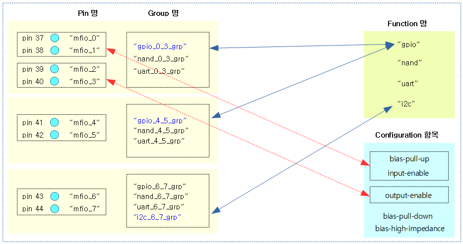
Virtual Pinctrl 드라이버 매핑 예)
pinctrl 드라이버가 다음과 같이 8개의 핀들을 관리한다고 가정한다.
- pinmux
- 처음 6개의 핀을 gpio 기능을 선택하였다. 그리고 마지막 2개의 핀은 i2c 기능으로 선택하였다.
- pinconf
- 처음 2개의 핀을 bias-pull-up, input-enable 설정하였다. 그리고 다음 2개의 핀을 output-enable 설정하였다.
디바이스 트리 설정
다음과 같이 “foo,foo-pinctrl” 드라이버 노드에 pinmux/pinconf 노드들을 구성하였다.
- pinctrl 드라이버가 로드되자마자 2개의 pinmux 노드와 2개의 pinconf 노드를 동작시킨다.
foo-pinctrl {
	compatible = "foo,foo-pinctrl";
	reg = <0x0 0xf000e000 0x0 0x100>;

	pinctrl-names = "default";
	pinctrl-0 = <&gpio_0_5_sel &i2c_sel
		     &mfio_0_1_conf &mfio_2_3_conf>;

	gpio_sel: gpio_sel {
		function = "gpio";
		groups = "gpio_0_3_grp",
			 "gpio_4_5_grp",
			 "gpio_6_7_grp";
	};

	gpio_0_5_sel: gpio_0_5_sel {
		function = "gpio";
		groups = "gpio_0_3_grp",
			 "gpio_4_5_grp";
	};

	nand_sel: nand_sel {
		function = "nand";
		groups = "nand_0_3_grp",
			 "nand_4_5_grp",
			 "nand_6_7_grp";
	};

	uart_sel: uart_sel {
		function = "uart";
		groups = "uart_0_3_grp",
			 "uart_4_5_grp",
			 "uart_6_7_grp";
	};

	i2c_sel: i2c_sel {
		function = "i2c";
		groups = "i2c_6_7_grp";
	};

	mfio_0_1_conf: mfio_0_1_conf {
		pins = "mfio_0",
		       "mfio_1";
		input-enable;
		bias-pull-up;
	};

	mfio_2_3_conf: mfio_2_3_conf {
		pins = "mfio_2",
		       "mfio_3";
		output-enable;
	};
};
가상 “foo,foo-pinctrl” 드라이버 로드
드라이버가 로드될 때 동작할 pinmux/pinconf 노드를 파싱하여 동작시킨다.
- 디바이스 트리의 설정 3개의 그룹에 pinmux 설정이 적용되고, 6개의 pinconf 설정이 적용되었다.
$ insmod foo-pinctrl.ko
[  223.767526] foo_pinctrl: loading out-of-tree module taints kernel.
[  223.820087] foo-pinctrl f000e000.foo-pinctrl: func:0 name:gpio grp:0 name:gpio_0_3_grp
[  223.820546] foo-pinctrl f000e000.foo-pinctrl: func:0 name:gpio grp:3 name:gpio_4_5_grp
[  223.820757] foo-pinctrl f000e000.foo-pinctrl: func:3 name:i2c grp:9 name:i2c_6_7_grp
[  223.821018] foo-pinctrl f000e000.foo-pinctrl: pin:0 set bias-pull-up
[  223.821182] foo-pinctrl f000e000.foo-pinctrl: pin:0 set input-enable
[  223.821373] foo-pinctrl f000e000.foo-pinctrl: pin:1 set bias-pull-up
[  223.871234] foo-pinctrl f000e000.foo-pinctrl: pin:1 set input-enable
[  223.871659] foo-pinctrl f000e000.foo-pinctrl: pin:2 set output-enable
[  223.871891] foo-pinctrl f000e000.foo-pinctrl: pin:3 set output-enable
디버그 출력
$ cd /sys/kernel/debug/pinctrl
$ ls -la
total 0
drwxr-xr-x  3 root root 0 Jan  1  1970 .
drwx------ 22 root root 0 Jan  1  1970 ..
drwxr-xr-x  2 root root 0 Jul  9 06:59 f000e000.foo-pinctrl
-r--r--r--  1 root root 0 Jan  1  1970 pinctrl-devices
-r--r--r--  1 root root 0 Jan  1  1970 pinctrl-handles
-r--r--r--  1 root root 0 Jan  1  1970 pinctrl-maps
$ cat pinctrl-devices
name [pinmux] [pinconf]
foo-pinmux yes yes
$ cat pinctrl-handles
Requested pin control handlers their pinmux maps:
device: f000e000.foo-pinctrl current state: default
  state: default
    type: MUX_GROUP controller foo-pinmux group: gpio_0_3_grp (0) function: gpio (0)
    type: MUX_GROUP controller foo-pinmux group: gpio_4_5_grp (3) function: gpio (0)
    type: MUX_GROUP controller foo-pinmux group: i2c_6_7_grp (9) function: i2c (3)
    type: CONFIGS_PIN controller foo-pinmux pin mfio_0 (0)config 00000105
config 0000010b
    type: CONFIGS_PIN controller foo-pinmux pin mfio_1 (1)config 00000105
config 0000010b
    type: CONFIGS_PIN controller foo-pinmux pin mfio_2 (2)config 0000010f
    type: CONFIGS_PIN controller foo-pinmux pin mfio_3 (3)config 0000010f
$ cat pinctrl-maps
Pinctrl maps:
device f000e000.foo-pinctrl
state default
type MUX_GROUP (2)
controlling device f000e000.foo-pinctrl
group gpio_0_3_grp
function gpio

device f000e000.foo-pinctrl
state default
type MUX_GROUP (2)
controlling device f000e000.foo-pinctrl
group gpio_4_5_grp
function gpio

device f000e000.foo-pinctrl
state default
type MUX_GROUP (2)
controlling device f000e000.foo-pinctrl
group i2c_6_7_grp
function i2c

device f000e000.foo-pinctrl
state default
type CONFIGS_PIN (3)
controlling device f000e000.foo-pinctrl
pin mfio_0
config 00000105
config 0000010b

device f000e000.foo-pinctrl
state default
type CONFIGS_PIN (3)
controlling device f000e000.foo-pinctrl
pin mfio_1
config 00000105
config 0000010b

device f000e000.foo-pinctrl
state default
type CONFIGS_PIN (3)
controlling device f000e000.foo-pinctrl
pin mfio_2
config 0000010f

device f000e000.foo-pinctrl
state default
type CONFIGS_PIN (3)
controlling device f000e000.foo-pinctrl
pin mfio_3
config 0000010f
“f000e000.foo-pinctrl” 드라이버 정보
$ cd f000e000.foo-pinctrl
$ ls -la
total 0
drwxr-xr-x 2 root root 0 Jul  9 06:59 .
drwxr-xr-x 3 root root 0 Jan  1  1970 ..
-r--r--r-- 1 root root 0 Jul  9 06:59 gpio-ranges
-rw-rw-r-- 1 root root 0 Jul  9 06:59 pinconf-config
-r--r--r-- 1 root root 0 Jul  9 06:59 pinconf-groups
-r--r--r-- 1 root root 0 Jul  9 06:59 pinconf-pins
-r--r--r-- 1 root root 0 Jul  9 06:59 pingroups
-r--r--r-- 1 root root 0 Jul  9 06:59 pinmux-functions
-r--r--r-- 1 root root 0 Jul  9 06:59 pinmux-pins
-r--r--r-- 1 root root 0 Jul  9 06:59 pins
pin과 그룹 디버그 정보
$ cat pins
registered pins: 8
pin 0 (mfio_0)  f000e000.foo-pinctrl
pin 1 (mfio_1)  f000e000.foo-pinctrl
pin 2 (mfio_2)  f000e000.foo-pinctrl
pin 3 (mfio_3)  f000e000.foo-pinctrl
pin 4 (mfio_4)  f000e000.foo-pinctrl
pin 5 (mfio_5)  f000e000.foo-pinctrl
pin 6 (mfio_6)  f000e000.foo-pinctrl
pin 7 (mfio_7)  f000e000.foo-pinctrl
$ cat pingroups
registered pin groups:
group: gpio_0_3_grp
pin 0 (mfio_0)
pin 1 (mfio_1)
pin 2 (mfio_2)
pin 3 (mfio_3)

group: nand_0_3_grp
pin 0 (mfio_0)
pin 1 (mfio_1)
pin 2 (mfio_2)
pin 3 (mfio_3)

group: uart_0_3_grp
pin 0 (mfio_0)
pin 1 (mfio_1)
pin 2 (mfio_2)
pin 3 (mfio_3)

group: gpio_4_5_grp
pin 4 (mfio_4)
pin 5 (mfio_5)

group: nand_4_5_grp
pin 4 (mfio_4)
pin 5 (mfio_5)

group: uart_4_5_grp
pin 4 (mfio_4)
pin 5 (mfio_5)

group: gpio_6_7_grp
pin 6 (mfio_6)
pin 7 (mfio_7)

group: nand_6_7_grp
pin 6 (mfio_6)
pin 7 (mfio_7)

group: uart_6_7_grp
pin 6 (mfio_6)
pin 7 (mfio_7)

group: i2c_6_7_grp
pin 6 (mfio_6)
pin 7 (mfio_7)
pinmux 디버그 정보
$ cat pinmux-functions
function: gpio, groups = [ gpio_0_3_grp gpio_4_5_grp gpio_6_7_grp ]
function: nand, groups = [ nand_0_3_grp nand_4_5_grp nand_6_7_grp ]
function: uart, groups = [ uart_0_3_grp uart_4_5_grp uart_6_7_grp ]
function: i2c, groups = [ i2c_6_7_grp ]
$ cat pinmux-pins
Pinmux settings per pin
Format: pin (name): mux_owner gpio_owner hog?
pin 0 (mfio_0): f000e000.foo-pinctrl (GPIO UNCLAIMED) function gpio group gpio_0_3_grp
pin 1 (mfio_1): f000e000.foo-pinctrl (GPIO UNCLAIMED) function gpio group gpio_0_3_grp
pin 2 (mfio_2): f000e000.foo-pinctrl (GPIO UNCLAIMED) function gpio group gpio_0_3_grp
pin 3 (mfio_3): f000e000.foo-pinctrl (GPIO UNCLAIMED) function gpio group gpio_0_3_grp
pin 4 (mfio_4): f000e000.foo-pinctrl (GPIO UNCLAIMED) function gpio group gpio_4_5_grp
pin 5 (mfio_5): f000e000.foo-pinctrl (GPIO UNCLAIMED) function gpio group gpio_4_5_grp
pin 6 (mfio_6): f000e000.foo-pinctrl (GPIO UNCLAIMED) function i2c group i2c_6_7_grp
pin 7 (mfio_7): f000e000.foo-pinctrl (GPIO UNCLAIMED) function i2c group i2c_6_7_grp
pinconf 디버그 정보
$ cat pinconf-groups
Pin config settings per pin group
Format: group (name): configs
0 (gpio_0_3_grp):
1 (nand_0_3_grp):
2 (uart_0_3_grp):
3 (gpio_4_5_grp):
4 (nand_4_5_grp):
5 (uart_4_5_grp):
6 (gpio_6_7_grp):
7 (nand_6_7_grp):
8 (uart_6_7_grp):
$ cat pinconf-pins
[  713.351594] foo-pinctrl f000e000.foo-pinctrl: pin=0, config=bias-high-impedance:0
[  713.354329] foo-pinctrl f000e000.foo-pinctrl: pin=0, config=bias-pull-down:1
[  713.364921] foo-pinctrl f000e000.foo-pinctrl: pin=0, config=bias-pull-up:1
[  713.367024] foo-pinctrl f000e000.foo-pinctrl: pin=0, config=input-enable:0
[  713.381472] foo-pinctrl f000e000.foo-pinctrl: pin=0, config=output-enable:1
[  713.382058] foo-pinctrl f000e000.foo-pinctrl: pin=1, config=bias-high-impedance:0
[  713.382344] foo-pinctrl f000e000.foo-pinctrl: pin=1, config=bias-pull-down:1
[  713.382673] foo-pinctrl f000e000.foo-pinctrl: pin=1, config=bias-pull-up:1
[  713.383044] foo-pinctrl f000e000.foo-pinctrl: pin=1, config=input-enable:0
[  713.385809] foo-pinctrl f000e000.foo-pinctrl: pin=1, config=output-enable:1
[  713.402990] foo-pinctrl f000e000.foo-pinctrl: pin=2, config=bias-high-impedance:1
[  713.403291] foo-pinctrl f000e000.foo-pinctrl: pin=2, config=bias-pull-down:0
[  713.405833] foo-pinctrl f000e000.foo-pinctrl: pin=2, config=bias-pull-up:0
[  713.406044] foo-pinctrl f000e000.foo-pinctrl: pin=2, config=input-enable:1
[  713.406221] foo-pinctrl f000e000.foo-pinctrl: pin=2, config=output-enable:0
[  713.406366] foo-pinctrl f000e000.foo-pinctrl: pin=3, config=bias-high-impedance:1
[  713.406553] foo-pinctrl f000e000.foo-pinctrl: pin=3, config=bias-pull-down:0
[  713.406667] foo-pinctrl f000e000.foo-pinctrl: pin=3, config=bias-pull-up:0
[  713.406827] foo-pinctrl f000e000.foo-pinctrl: pin=3, config=input-enable:1
[  713.406950] foo-pinctrl f000e000.foo-pinctrl: pin=3, config=output-enable:0
[  713.407103] foo-pinctrl f000e000.foo-pinctrl: pin=4, config=bias-high-impedance:1
[  713.407224] foo-pinctrl f000e000.foo-pinctrl: pin=4, config=bias-pull-down:0
[  713.420170] foo-pinctrl f000e000.foo-pinctrl: pin=4, config=bias-pull-up:0
[  713.420738] foo-pinctrl f000e000.foo-pinctrl: pin=4, config=input-enable:0
[  713.421027] foo-pinctrl f000e000.foo-pinctrl: pin=4, config=output-enable:1
[  713.421257] foo-pinctrl f000e000.foo-pinctrl: pin=5, config=bias-high-impedance:1
[  713.421490] foo-pinctrl f000e000.foo-pinctrl: pin=5, config=bias-pull-down:0
[  713.421755] foo-pinctrl f000e000.foo-pinctrl: pin=5, config=bias-pull-up:0
[  713.421944] foo-pinctrl f000e000.foo-pinctrl: pin=5, config=input-enable:0
[  713.422117] foo-pinctrl f000e000.foo-pinctrl: pin=5, config=output-enable:1
[  713.422226] foo-pinctrl f000e000.foo-pinctrl: pin=6, config=bias-high-impedance:1
[  713.422300] foo-pinctrl f000e000.foo-pinctrl: pin=6, config=bias-pull-down:0
[  713.422469] foo-pinctrl f000e000.foo-pinctrl: pin=6, config=bias-pull-up:0
[  713.422555] foo-pinctrl f000e000.foo-pinctrl: pin=6, config=input-enable:0
[  713.422726] foo-pinctrl f000e000.foo-pinctrl: pin=6, config=output-enable:1
[  713.422844] foo-pinctrl f000e000.foo-pinctrl: pin=7, config=bias-high-impedance:1
[  713.422969] foo-pinctrl f000e000.foo-pinctrl: pin=7, config=bias-pull-down:0
[  713.423114] foo-pinctrl f000e000.foo-pinctrl: pin=7, config=bias-pull-up:0
[  713.423229] foo-pinctrl f000e000.foo-pinctrl: pin=7, config=input-enable:0
[  713.425177] foo-pinctrl f000e000.foo-pinctrl: pin=7, config=output-enable:1
Pin config settings per pin
Format: pin (name): configs
pin 0 (mfio_0): input bias high impedance, input bias pull down, input bias pull up, input enabled, output enabled
pin 1 (mfio_1): input bias high impedance, input bias pull down, input bias pull up, input enabled, output enabled
pin 2 (mfio_2): input bias high impedance, input bias pull down, input bias pull up, input enabled, output enabled
pin 3 (mfio_3): input bias high impedance, input bias pull down, input bias pull up, input enabled, output enabled
pin 4 (mfio_4): input bias high impedance, input bias pull down, input bias pull up, input enabled, output enabled
pin 5 (mfio_5): input bias high impedance, input bias pull down, input bias pull up, input enabled, output enabled
pin 6 (mfio_6): input bias high impedance, input bias pull down, input bias pull up, input enabled, output enabled
pin 7 (mfio_7): input bias high impedance, input bias pull down, input bias pull up, input enabled, output enabled
참고: GPIO 유저 스페이스에서 활용
# cd /sys/class/gpio/
# ls
root@raspberrypi:/sys/class/gpio# ls
export	gpiochip0  unexport
# echo 23 > export
# cd  gpio23
# ls
active_low  device  direction  edge  subsystem	uevent	value
# # cat active_low
0
# cat direction
in
# cat edge
none
# cat value
0
# cd ..
# echo 23 > unexport
참고
- Pin Control Subsystem -1- | 문c – 현재글
- Pin Control Subsystem -2- | 문c
- GPIO Subsystem -1- | 문c
- GPIO Subsystem -2- | 문c
- GPIO Subsystem -3- | 문c
- PINCTRL (PIN CONTROL) subsystem | Kernel.org
- Documentation/devicetree/bindings/pinctrl/pinctrl-bindings.txt | Kernel.org
- PIN CONTROL OVERVIEW | Linus Walleij, linaro – 다운로드 pdf
- Pin Control Sybsystem – Building Pins and GPIO from the ground up | Linaro & Erricsson – 다운로드 pdf
- Linux kernel: consolidation in the ARM architecture support | Thomas Petazzoni, Free Electrons – 다운로드 pdf