SPI Subsystem -2- (Driver)


SPI Controller Core

SPI Master & Slave 컨트롤러 등록

spi_register_controller()

호환을 위해 spi_register_master() 매크로 함수는 spi_register_controller()를 호출한다.

drivers/spi/spi.c

/**
 * spi_register_controller - register SPI master or slave controller
 * @ctlr: initialized master, originally from spi_alloc_master() or
 *      spi_alloc_slave()
 * Context: can sleep
 *
 * SPI controllers connect to their drivers using some non-SPI bus,
 * such as the platform bus.  The final stage of probe() in that code
 * includes calling spi_register_controller() to hook up to this SPI bus glue.
 *
 * SPI controllers use board specific (often SOC specific) bus numbers,
 * and board-specific addressing for SPI devices combines those numbers
 * with chip select numbers.  Since SPI does not directly support dynamic
 * device identification, boards need configuration tables telling which
 * chip is at which address.
 *
 * This must be called from context that can sleep.  It returns zero on
 * success, else a negative error code (dropping the controller's refcount).
 * After a successful return, the caller is responsible for calling
 * spi_unregister_controller().
 *
 * Return: zero on success, else a negative error code.
 */
int spi_register_controller(struct spi_controller *ctlr)
{
        struct device           *dev = ctlr->dev.parent;
        struct boardinfo        *bi;
        int                     status = -ENODEV;
        int                     id, first_dynamic;

        if (!dev)
                return -ENODEV;

        if (!spi_controller_is_slave(ctlr)) {
                status = of_spi_register_master(ctlr);
                if (status)
                        return status;
        }

        /* even if it's just one always-selected device, there must
         * be at least one chipselect
         */
        if (ctlr->num_chipselect == 0)
                return -EINVAL;
        /* allocate dynamic bus number using Linux idr */
        if ((ctlr->bus_num < 0) && ctlr->dev.of_node) {
                id = of_alias_get_id(ctlr->dev.of_node, "spi");
                if (id >= 0) {
                        ctlr->bus_num = id;
                        mutex_lock(&board_lock);
                        id = idr_alloc(&spi_master_idr, ctlr, ctlr->bus_num,
                                       ctlr->bus_num + 1, GFP_KERNEL);
                        mutex_unlock(&board_lock);
                        if (WARN(id < 0, "couldn't get idr"))
                                return id == -ENOSPC ? -EBUSY : id;
                }
        }
        if (ctlr->bus_num < 0) {
                first_dynamic = of_alias_get_highest_id("spi");
                if (first_dynamic < 0)
                        first_dynamic = 0;
                else
                        first_dynamic++;

                mutex_lock(&board_lock);
                id = idr_alloc(&spi_master_idr, ctlr, first_dynamic,
                               0, GFP_KERNEL);
                mutex_unlock(&board_lock);
                if (WARN(id < 0, "couldn't get idr"))
                        return id;
                ctlr->bus_num = id;
        }
        INIT_LIST_HEAD(&ctlr->queue);
        spin_lock_init(&ctlr->queue_lock);
        spin_lock_init(&ctlr->bus_lock_spinlock);
        mutex_init(&ctlr->bus_lock_mutex);
        mutex_init(&ctlr->io_mutex);
        ctlr->bus_lock_flag = 0;
        init_completion(&ctlr->xfer_completion);
        if (!ctlr->max_dma_len)
                ctlr->max_dma_len = INT_MAX;

SPI 마스터 또는 슬레이브 컨트롤러를 등록한다.

  • 코드 라인 11~15에서 등록할 컨트롤러가 슬레이브가 아닌 경우 디바이스 트리로부터 칩셀렉트를 위해 gpio 핀 정보들을 읽어온다.
    • 1개 이상의 “cs-gpios” 속성 값을 읽어 해당하는 gpio 핀 번호를 ctlr->cs_gpios[]에 대입한다.
  • 코드 라인 20~21에서 선택할 수 있는 슬레이브 칩 수가 0인 경우 에러를 반환한다.
  • 코드 라인 23~34에서 spi 버스 번호가 0을 초과한, 즉 다수인경우 “spi” alias 명을 찾아 id 값으로 버스 번호를 적용하여 idr 할당한다.
  • 코드 라인 35~49에서 spi 버스 번호가 0 미만인 경우 “spi” alias명으로 찾은 가장 높은 id 값 +1로 버스 번호를 적용하여 idr 할당한다.
  • 코드 라인 50~58에서 spi 컨트롤러의 멤버들을 초기화한다.


        /* register the device, then userspace will see it.
         * registration fails if the bus ID is in use.
         */
        dev_set_name(&ctlr->dev, "spi%u", ctlr->bus_num);
        status = device_add(&ctlr->dev);
        if (status < 0) {
                /* free bus id */
                mutex_lock(&board_lock);
                idr_remove(&spi_master_idr, ctlr->bus_num);
                mutex_unlock(&board_lock);
                goto done;
        }
        dev_dbg(dev, "registered %s %s\n",
                        spi_controller_is_slave(ctlr) ? "slave" : "master",
                        dev_name(&ctlr->dev));

        /* If we're using a queued driver, start the queue */
        if (ctlr->transfer)
                dev_info(dev, "controller is unqueued, this is deprecated\n");
        else {
                status = spi_controller_initialize_queue(ctlr);
                if (status) {
                        device_del(&ctlr->dev);
                        /* free bus id */
                        mutex_lock(&board_lock);
                        idr_remove(&spi_master_idr, ctlr->bus_num);
                        mutex_unlock(&board_lock);
                        goto done;
                }
        }
        /* add statistics */
        spin_lock_init(&ctlr->statistics.lock);

        mutex_lock(&board_lock);
        list_add_tail(&ctlr->list, &spi_controller_list);
        list_for_each_entry(bi, &board_list, list)
                spi_match_controller_to_boardinfo(ctlr, &bi->board_info);
        mutex_unlock(&board_lock);

        /* Register devices from the device tree and ACPI */
        of_register_spi_devices(ctlr);
        acpi_register_spi_devices(ctlr);
done:
        return status;
}
EXPORT_SYMBOL_GPL(spi_register_controller);
  • 코드 라인 4~15에서 “spi<bus#>”  명으로 디바이스를 추가한다.
    • 예) “registered  master spi0” 또는 “registered slave spi1” 형식으로 디버그 메시지를 출력한다.
  • 코드 라인 18~30에서 (*transfer) 후크 함수는 deprecated될 예정이다. 이 함수가 지정되지 않은 경우큐 방식을 사용하기 위해 spi 컨트롤러용 큐를 초기화한다.
  • 코드 라인 32에서 통계 관련 락을 초기화한다.
  • 코드 라인 34~38에서 전역 spi_controller_list에 컨트롤러를 추가한다. 그런 후 컨트롤러가 전역 board_list에 있는 디바이스와 매치되는 경우 spi_new_device() 함수를 호출하여 spi 디바이스로 추가 등록한다.
  • 코드 라인 41에서 컨트롤러 노드의 하위 노드의 SPI 디바이스들을 추가한다.
    • of_register_spi_device() -> 다음 각종 spi 디바이스 속성 값을 파싱한 후 -> spi_add_device()
      • “spi-cpha”
      • “spi-cpol”
      • “spi-cs-high”
      • “spi-3wire”
      • “spi-tx-bus-width”
      • “spi-rx-bus-width”
      • “slave”
      • “reg”
      • “spi-max-frequency”
  • 코드 라인 42에서 ACPI 펌웨어에서 spi 디바이스 정보를 읽어와서 추가한다.


of_register_spi_devices()

drivers/spi/spi.c

/**
 * of_register_spi_devices() - Register child devices onto the SPI bus
 * @ctlr:       Pointer to spi_controller device
 *
 * Registers an spi_device for each child node of controller node which
 * represents a valid SPI slave.
 */
static void of_register_spi_devices(struct spi_controller *ctlr)
{
        struct spi_device *spi;
        struct device_node *nc;

        if (!ctlr->dev.of_node)
                return;

        for_each_available_child_of_node(ctlr->dev.of_node, nc) {
                if (of_node_test_and_set_flag(nc, OF_POPULATED))
                        continue;
                spi = of_register_spi_device(ctlr, nc);
                if (IS_ERR(spi)) {
                        dev_warn(&ctlr->dev,
                                 "Failed to create SPI device for %pOF\n", nc);
                        of_node_clear_flag(nc, OF_POPULATED);
                }
        }
}

컨트롤러 디바이스 트리 노드의 하위 노드들을 대상으로 매치되는 spi 디바이스들을 모두 등록한다.


of_register_spi_device()

drivers/spi/spi.c

static struct spi_device *
of_register_spi_device(struct spi_controller *ctlr, struct device_node *nc)
{
        struct spi_device *spi;
        int rc;

        /* Alloc an spi_device */
        spi = spi_alloc_device(ctlr);
        if (!spi) {
                dev_err(&ctlr->dev, "spi_device alloc error for %pOF\n", nc);
                rc = -ENOMEM;
                goto err_out;
        }

        /* Select device driver */
        rc = of_modalias_node(nc, spi->modalias,
                                sizeof(spi->modalias));
        if (rc < 0) {
                dev_err(&ctlr->dev, "cannot find modalias for %pOF\n", nc);
                goto err_out;
        }

        rc = of_spi_parse_dt(ctlr, spi, nc);
        if (rc)
                goto err_out;

        /* Store a pointer to the node in the device structure */
        of_node_get(nc);
        spi->dev.of_node = nc;

        /* Register the new device */
        rc = spi_add_device(spi);
        if (rc) {
                dev_err(&ctlr->dev, "spi_device register error %pOF\n", nc);
                goto err_of_node_put;
        }

        return spi;

err_of_node_put:
        of_node_put(nc);
err_out:
        spi_dev_put(spi);
        return ERR_PTR(rc);
}

컨트롤러 디바이스 트리 노드의 지정한 하위 노드의 spi 디바이스 하나를 등록한다.

  • 코드 라인 8~13에서 spi 디바이스를 할당 받아 초기화한다.
  • 코드 라인 16~21에서 “compatible” 속성 값에서 회사명과 컴마(“,”)를 제외한 드라이버명을 spi->modalias에 대입한다.
  • 코드 라인 23~25에서 spi 디바이스 노드에서 다음 속성들을 파싱해온다.
    • “spi-cpha”
    • “spi-cpol”
    • “spi-cs-high”
    • “spi-3wire”
    • “spi-tx-bus-width”
    • “spi-rx-bus-width”
    • “slave”
    • “reg”
    • “spi-max-frequency”
  • 코드 라인 28~29에서 spi 디바이스의 참조 카운터를 1 증가시키고, 디바이스 트리의 spi 디바이스 노드를 가리키게 한다.
  • 코드 라인 32~36에서 spi 디바이스를 추가한다.


spi_add_device()

drivers/spi/spi.c

/**
 * spi_add_device - Add spi_device allocated with spi_alloc_device
 * @spi: spi_device to register
 *
 * Companion function to spi_alloc_device.  Devices allocated with
 * spi_alloc_device can be added onto the spi bus with this function.
 *
 * Return: 0 on success; negative errno on failure
 */
int spi_add_device(struct spi_device *spi)
{
        static DEFINE_MUTEX(spi_add_lock);
        struct spi_controller *ctlr = spi->controller;
        struct device *dev = ctlr->dev.parent;
        int status;

        /* Chipselects are numbered 0..max; validate. */
        if (spi->chip_select >= ctlr->num_chipselect) {
                dev_err(dev, "cs%d >= max %d\n", spi->chip_select,
                        ctlr->num_chipselect);
                return -EINVAL;
        }

        /* Set the bus ID string */
        spi_dev_set_name(spi);

        /* We need to make sure there's no other device with this
         * chipselect **BEFORE** we call setup(), else we'll trash
         * its configuration.  Lock against concurrent add() calls.
         */
        mutex_lock(&spi_add_lock);

        status = bus_for_each_dev(&spi_bus_type, NULL, spi, spi_dev_check);
        if (status) {
                dev_err(dev, "chipselect %d already in use\n",
                                spi->chip_select);
                goto done;
        }

        if (ctlr->cs_gpios)
                spi->cs_gpio = ctlr->cs_gpios[spi->chip_select];

        /* Drivers may modify this initial i/o setup, but will
         * normally rely on the device being setup.  Devices
         * using SPI_CS_HIGH can't coexist well otherwise...
         */
        status = spi_setup(spi);
        if (status < 0) {
                dev_err(dev, "can't setup %s, status %d\n",
                                dev_name(&spi->dev), status);
                goto done;
        }

        /* Device may be bound to an active driver when this returns */
        status = device_add(&spi->dev);
        if (status < 0)
                dev_err(dev, "can't add %s, status %d\n",
                                dev_name(&spi->dev), status);
        else
                dev_dbg(dev, "registered child %s\n", dev_name(&spi->dev));

done:
        mutex_unlock(&spi_add_lock);
        return status;
}
EXPORT_SYMBOL_GPL(spi_add_device);

spi 디바이스를 칩셀렉션하고 hw 설정한 후 추가한다.

  • 코드 라인 9~13에서 최대 슬레이브 칩 수를 초과하는 칩이 선택된 경우 에러를 반환한다.
  • 코드 라인 16에서 버스 번호를 포함하여 spi 디바이스 명을 결정하는데 다음 둘 중 하나를 사용한다.
    • acpi를 사용하는 경우 “spi-<device name>” 포맷을 사용한다.
    • 그 외의 경우 “<컨트롤러명>.<칩 셀렉트 번호>” 포맷을 사용한다.
  • 코드 라인 24~29에서 spi 디바이스가 이미 셋업되어 사용중인지 확인한다. 사용중이면 경고 메시지를 출력하고 등록을 포기한다.
  • 코드 라인 31~32에서 gpio를 사용하여 칩셀렉트를 하는 경우 사용할 gpio 번호를 지정한다.
  • 코드 라인 38~43에서 spi 디바이스를 hw 설정한다.
  • 코드 라인 46~51에서 spi 디바이스를 추가한다.


spi_setup()

drivers/spi/spi.c

/**
 * spi_setup - setup SPI mode and clock rate
 * @spi: the device whose settings are being modified
 * Context: can sleep, and no requests are queued to the device
 *
 * SPI protocol drivers may need to update the transfer mode if the
 * device doesn't work with its default.  They may likewise need
 * to update clock rates or word sizes from initial values.  This function
 * changes those settings, and must be called from a context that can sleep.
 * Except for SPI_CS_HIGH, which takes effect immediately, the changes take
 * effect the next time the device is selected and data is transferred to
 * or from it.  When this function returns, the spi device is deselected.
 *
 * Note that this call will fail if the protocol driver specifies an option
 * that the underlying controller or its driver does not support.  For
 * example, not all hardware supports wire transfers using nine bit words,
 * LSB-first wire encoding, or active-high chipselects.
 *
 * Return: zero on success, else a negative error code.
 */
int spi_setup(struct spi_device *spi)
{
        unsigned        bad_bits, ugly_bits;
        int             status;

        /* check mode to prevent that DUAL and QUAD set at the same time
         */
        if (((spi->mode & SPI_TX_DUAL) && (spi->mode & SPI_TX_QUAD)) ||
                ((spi->mode & SPI_RX_DUAL) && (spi->mode & SPI_RX_QUAD))) {
                dev_err(&spi->dev,
                "setup: can not select dual and quad at the same time\n");
                return -EINVAL;
        }
        /* if it is SPI_3WIRE mode, DUAL and QUAD should be forbidden
         */
        if ((spi->mode & SPI_3WIRE) && (spi->mode &
                (SPI_TX_DUAL | SPI_TX_QUAD | SPI_RX_DUAL | SPI_RX_QUAD)))
                return -EINVAL;
        /* help drivers fail *cleanly* when they need options
         * that aren't supported with their current controller
         */
        bad_bits = spi->mode & ~spi->controller->mode_bits;
        ugly_bits = bad_bits &
                    (SPI_TX_DUAL | SPI_TX_QUAD | SPI_RX_DUAL | SPI_RX_QUAD);
        if (ugly_bits) {
                dev_warn(&spi->dev,
                         "setup: ignoring unsupported mode bits %x\n",
                         ugly_bits);
                spi->mode &= ~ugly_bits;
                bad_bits &= ~ugly_bits;
        }
        if (bad_bits) {
                dev_err(&spi->dev, "setup: unsupported mode bits %x\n",
                        bad_bits);
                return -EINVAL;
        }

        if (!spi->bits_per_word)
                spi->bits_per_word = 8;

        status = __spi_validate_bits_per_word(spi->controller,
                                              spi->bits_per_word);
        if (status)
                return status;

        if (!spi->max_speed_hz)
                spi->max_speed_hz = spi->controller->max_speed_hz;

        if (spi->controller->setup)
                status = spi->controller->setup(spi);

        spi_set_cs(spi, false);

        dev_dbg(&spi->dev, "setup mode %d, %s%s%s%s%u bits/w, %u Hz max --> %d\n",
                        (int) (spi->mode & (SPI_CPOL | SPI_CPHA)),
                        (spi->mode & SPI_CS_HIGH) ? "cs_high, " : "",
                        (spi->mode & SPI_LSB_FIRST) ? "lsb, " : "",
                        (spi->mode & SPI_3WIRE) ? "3wire, " : "",
                        (spi->mode & SPI_LOOP) ? "loopback, " : "",
                        spi->bits_per_word, spi->max_speed_hz,
                        status);

        return status;
}

spi 디바이스의 클럭 모드 및 속도 등을 설정한다.

  • 코드 라인 8~13에서 spi 디바이스가 동시에 dual 및 quad 설정을 요청하는 경우 에러 미세지를 출력하고 에러를 반환한다.
  • 코드 라인 16~18에서 3wire 모드가 선택된 경우 dual 및 quad와 같이 설정할 수 없다.
  • 코드 라인 22~36에서 spi 컨트롤러가 지원하지 않는 모드를 요청한 경우 에러 메시지를 출력하고 에러를 반환한다.
    • 단 컨트롤러가 지원하지 않는 dual 또는 quad 요청을 한 경우 에러를 반환하지 않고 모드 플래그에서 제거한다.
  • 코드 라인 38~39에서 워드당 비트 수를 0으로 요청한 경우 디폴트로 8 비트를 사용한다.
  • 코드 라인 41~44에서 컨트롤러에 워드당 비트수 제한 마스크 이내에서 사용되어야 하고 워드당 비트 수가 32를 초과한 경우 에러를 반환한다.
  • 코드 라인 46~47에서 spi 디바이스의 속도 제한 값이 없는 경우 spi 컨트롤러의 값을 사용한다.
  • 코드 라인 49~50에서 spi 디바이스 설정 값으로 spi 컨트롤러를 설정한다.
  • 코드 라인 52에서 spi 디바이스의 칩 셀렉트를 하지 않도록 설정한다.
  • 코드 라인 54에서 설정 정보를 출력한다.
    • “setup mode %d, “%s%s%s%s%u bits/w, %d Hz max –> %d”
      • 1) cpol 또는 cpha 모드 비트만을 출력한다.
      • 2) cs_high 여부
      • 3) lsb 부터 출력하는지 여부
      • 4) 3wire 모드 여부
      • 5) loopback 모드 여부
      • 6) 워드당 비트 수
      • 7) 최대 제한 속도
      • 8) 설정 상태 값


Kernel API

SPI 전송

spi_async()

  • 비동기 메시지 전송 요청
  • 메시지 전송이 완료되면 지정한 콜백 함수가 호출된다.
  • irq context 또는 process context 모두에서 사용할 수 있다.

drivers/spi/spi.c

/**
 * spi_async - asynchronous SPI transfer
 * @spi: device with which data will be exchanged
 * @message: describes the data transfers, including completion callback
 * Context: any (irqs may be blocked, etc)
 *
 * This call may be used in_irq and other contexts which can't sleep,
 * as well as from task contexts which can sleep.
 *
 * The completion callback is invoked in a context which can't sleep.
 * Before that invocation, the value of message->status is undefined.
 * When the callback is issued, message->status holds either zero (to
 * indicate complete success) or a negative error code.  After that
 * callback returns, the driver which issued the transfer request may
 * deallocate the associated memory; it's no longer in use by any SPI
 * core or controller driver code.
 *
 * Note that although all messages to a spi_device are handled in
 * FIFO order, messages may go to different devices in other orders.
 * Some device might be higher priority, or have various "hard" access
 * time requirements, for example.
 *
 * On detection of any fault during the transfer, processing of
 * the entire message is aborted, and the device is deselected.
 * Until returning from the associated message completion callback,
 * no other spi_message queued to that device will be processed.
 * (This rule applies equally to all the synchronous transfer calls,
 * which are wrappers around this core asynchronous primitive.)
 *
 * Return: zero on success, else a negative error code.
 */
int spi_async(struct spi_device *spi, struct spi_message *message)
{
        struct spi_controller *ctlr = spi->controller;
        int ret;
        unsigned long flags;

        ret = __spi_validate(spi, message);
        if (ret != 0)
                return ret;

        spin_lock_irqsave(&ctlr->bus_lock_spinlock, flags);

        if (ctlr->bus_lock_flag)
                ret = -EBUSY;
        else
                ret = __spi_async(spi, message);

        spin_unlock_irqrestore(&ctlr->bus_lock_spinlock, flags);

        return ret;
}
EXPORT_SYMBOL_GPL(spi_async);

준비된 @message를 @spi 슬레이브 장치로 비동기 전송한다. 결과가 0이면 정상이다.

  • 코드 라인 7~9에서 @message가 적절한지 유효 검사를 수행한다.
  • 코드 라인 11~18에서 spinlock을 획득한 채로 SPI 비동기 전송을 수행한다.
  • 코드 라인 20에서 결과를 반환한다. (결과 0이면 정상)


__spi_async()

drivers/spi/spi.c

static int __spi_async(struct spi_device *spi, struct spi_message *message)
{
        struct spi_controller *ctlr = spi->controller;

        message->spi = spi;

        SPI_STATISTICS_INCREMENT_FIELD(&ctlr->statistics, spi_async);
        SPI_STATISTICS_INCREMENT_FIELD(&spi->statistics, spi_async);

        trace_spi_message_submit(message);

        return ctlr->transfer(spi, message);
}

준비된 @message를 @spi 슬레이브 장치로 비동기 전송한다. 결과가 0이면 정상이다.

  • 코드 라인 3에서 spi 슬레이브 장치가 소속한 spi 컨트롤러를 알아온다.
  • 코드 라인 7~8에서 spi 컨트롤러와 슬레이브측의 spi_async 카운터를 각각 1씩 증가시킨다.
  • 코드 라인 10에서 trace 메시지를 출력한다.
  • 코드 라인 12에서 컨트롤러에 구현된 (*transfer) 함수를 사용하여 @message를 @spi 슬레이브 디바이스에 비동기 전송한다.


spi_sync()

  • 동기 메시지 전송 요청
  • 슬립 가능한 프로세스 context에서만 사용할 수 있다.
    • irq context에서 사용하면 안된다.

drivers/spi/spi.c

/**
 * spi_sync - blocking/synchronous SPI data transfers
 * @spi: device with which data will be exchanged
 * @message: describes the data transfers
 * Context: can sleep
 *
 * This call may only be used from a context that may sleep.  The sleep
 * is non-interruptible, and has no timeout.  Low-overhead controller
 * drivers may DMA directly into and out of the message buffers.
 *
 * Note that the SPI device's chip select is active during the message,
 * and then is normally disabled between messages.  Drivers for some
 * frequently-used devices may want to minimize costs of selecting a chip,
 * by leaving it selected in anticipation that the next message will go
 * to the same chip.  (That may increase power usage.)
 *
 * Also, the caller is guaranteeing that the memory associated with the
 * message will not be freed before this call returns.
 *
 * Return: zero on success, else a negative error code.
 */
int spi_sync(struct spi_device *spi, struct spi_message *message)
{
        int ret;

        mutex_lock(&spi->controller->bus_lock_mutex);
        ret = __spi_sync(spi, message);
        mutex_unlock(&spi->controller->bus_lock_mutex);

        return ret;
}
EXPORT_SYMBOL_GPL(spi_sync);

준비된 @message를 @spi 슬레이브 장치로 동기 전송한다. 결과가 0이면 정상이다.

  • 코드 라인 5~7에서 spi 컨트롤러의 버스 락을 획득한채로 @spi 슬레이브 디바이스에게 @message를 동기 전송한다.
  • 코드 라인 9에서 결과 값을 반환한다.


__spi_sync()

drivers/spi/spi.c

static int __spi_sync(struct spi_device *spi, struct spi_message *message)
{
        DECLARE_COMPLETION_ONSTACK(done);
        int status;
        struct spi_controller *ctlr = spi->controller;
        unsigned long flags;

        status = __spi_validate(spi, message);
        if (status != 0)
                return status;

        message->complete = spi_complete;
        message->context = &done;
        message->spi = spi;

        SPI_STATISTICS_INCREMENT_FIELD(&ctlr->statistics, spi_sync);
        SPI_STATISTICS_INCREMENT_FIELD(&spi->statistics, spi_sync);

        /* If we're not using the legacy transfer method then we will
         * try to transfer in the calling context so special case.
         * This code would be less tricky if we could remove the
         * support for driver implemented message queues.
         */
        if (ctlr->transfer == spi_queued_transfer) {
                spin_lock_irqsave(&ctlr->bus_lock_spinlock, flags);

                trace_spi_message_submit(message);

                status = __spi_queued_transfer(spi, message, false);

                spin_unlock_irqrestore(&ctlr->bus_lock_spinlock, flags);
        } else {
                status = spi_async_locked(spi, message);
        }

        if (status == 0) {
                /* Push out the messages in the calling context if we
                 * can.
                 */
                if (ctlr->transfer == spi_queued_transfer) {
                        SPI_STATISTICS_INCREMENT_FIELD(&ctlr->statistics,
                                                       spi_sync_immediate);
                        SPI_STATISTICS_INCREMENT_FIELD(&spi->statistics,
                                                       spi_sync_immediate);
                        __spi_pump_messages(ctlr, false);
                }

                wait_for_completion(&done);
                status = message->status;
        }
        message->context = NULL;
        return status;
}

준비된 @message를 @spi 슬레이브 장치로 동기 전송한다. 결과가 0이면 정상이다.

  • 코드 라인 3에서 동기 전송의 완료를 대기하기 위해 사용할 값을 준비한다.
  • 코드 라인 5에서 @spi 슬레이브 장치가 소속한 spi 컨트롤러를 알아온다.
  • 코드 라인 8~10에서 @message의 유효성 검사를 수행한다.
  • 코드 라인 12~14에서 메시지에 전송완료를 대기 준비와 spi 슬레이브 디바이스를 지정한다.
  • 코드 라인 16~17에서 spi 컨트롤러와 슬레이브측의 spi_sync 카운터를 각각 1씩 증가시킨다.
  • 코드 라인 24~31에서 queued 전송이 가능한 spi 컨트롤러인 경우 이 방식으로 @message를 @spi 슬레이브 디바이스에 전송을 하도록 큐에 추가한다.
  • 코드 라인 32~34에서 queued 전송이 가능하지 않은 spi 컨트롤러인 경우 @message를 @spi 슬레이브 디바이스에 비동기 전송을 요청한다.
  • 코드 라인 36~50에서 성공적으로 전송 요청을 하였으면 전송이 완료될 때까지 대기한다. queued 전송이 가능한 spi 컨트롤러의 경우 spi 컨트롤러와 슬레이브측의 spi_sync_immediate 카운터를 각각 1씩 증가시킨다.
  • 코드 라인 51~52에서 message의 context를 null로 하고, 결과 값을 반환한다.


spi_complete()

drivers/spi/spi.c

/* Utility methods for SPI protocol drivers, layered on
 * top of the core.  Some other utility methods are defined as
 * inline functions.
 */

static void spi_complete(void *arg)
{
        complete(arg);
}

spi 전송이 실제 완료된 경우 complete를 호출한다.


spi_queued_transfer()

drivers/spi/spi.c

/**
 * spi_queued_transfer - transfer function for queued transfers
 * @spi: spi device which is requesting transfer
 * @msg: spi message which is to handled is queued to driver queue
 *
 * Return: zero on success, else a negative error code.
 */
static int spi_queued_transfer(struct spi_device *spi, struct spi_message *msg)
{
        return __spi_queued_transfer(spi, msg, true);
}

@spi 디바이스로 전송할 @msg를 spi 컨트롤러의 큐에 추가한다. 또한 컨트롤러의 spi 메시지 전송용 워커 스레드가 동작하지 않고 있으면 깨워 동작시킨다. 메시지를 큐에 잘 추가한 경우 성공 값 0을 반환한다.


__spi_queued_transfer()

drivers/spi/spi.c

static int __spi_queued_transfer(struct spi_device *spi,
                                 struct spi_message *msg,
                                 bool need_pump)
{
        struct spi_controller *ctlr = spi->controller;
        unsigned long flags;

        spin_lock_irqsave(&ctlr->queue_lock, flags);

        if (!ctlr->running) {
                spin_unlock_irqrestore(&ctlr->queue_lock, flags);
                return -ESHUTDOWN;
        }
        msg->actual_length = 0;
        msg->status = -EINPROGRESS;

        list_add_tail(&msg->queue, &ctlr->queue);
        if (!ctlr->busy && need_pump)
                kthread_queue_work(&ctlr->kworker, &ctlr->pump_messages);

        spin_unlock_irqrestore(&ctlr->queue_lock, flags);
        return 0;
}

@spi 디바이스로 전송할 @msg를 spi 컨트롤러의 큐에 추가한다. @need_pump가 요청되면 컨트롤러의 spi 메시지 전송용 워커 스레드가 동작하지 않고 있으면 깨워 동작시킨다. 메시지를 큐에 잘 추가한 경우 성공 값 0을 반환한다.

  • 코드 라인 5에서 @spi 슬레이브 디바이스가 소속한 spi 컨트롤러를 알아온다.
  • 코드 라인 8에서 spi 컨트롤러의 큐에 대한 락을 획득한다.
  • 코드 라인 10~13에서 spi 컨트롤러가 동작 중이지 않고 꺼져 있는 상태면, -ESHUTDOWN 에러를 반환한다.
  • 코드 라인 14~15에서 메시지의 전송 직전 초기 상태로 actual_legnth를 0으로 그리고 상태를 -EINPROGRESS로 지정한다.
  • 코드 라인 17에서 spi 컨트롤러의 큐에 @msg를 추가한다.
  • 코드 라인 18~19에서 @need_pump가 요청되면 컨트롤러의 spi 메시지 전송용 워커 스레드가 동작하지 않고 있으면 깨워 동작시킨다.
  • 코드 라인 21~22에서 spi 컨트롤러의 큐에 대한 락을 풀고, 성공 결과 값 0을 반환한다.


__spi_pump_messages()

drivers/spi/spi.c – 1/2

/**
 * __spi_pump_messages - function which processes spi message queue
 * @ctlr: controller to process queue for
 * @in_kthread: true if we are in the context of the message pump thread
 *
 * This function checks if there is any spi message in the queue that
 * needs processing and if so call out to the driver to initialize hardware
 * and transfer each message.
 *
 * Note that it is called both from the kthread itself and also from
 * inside spi_sync(); the queue extraction handling at the top of the
 * function should deal with this safely.
 */
static void __spi_pump_messages(struct spi_controller *ctlr, bool in_kthread)
{
        unsigned long flags;
        bool was_busy = false;
        int ret;

        /* Lock queue */
        spin_lock_irqsave(&ctlr->queue_lock, flags);

        /* Make sure we are not already running a message */
        if (ctlr->cur_msg) {
                spin_unlock_irqrestore(&ctlr->queue_lock, flags);
                return;
        }

        /* If another context is idling the device then defer */
        if (ctlr->idling) {
                kthread_queue_work(&ctlr->kworker, &ctlr->pump_messages);
                spin_unlock_irqrestore(&ctlr->queue_lock, flags);
                return;
        }

        /* Check if the queue is idle */
        if (list_empty(&ctlr->queue) || !ctlr->running) {
                if (!ctlr->busy) {
                        spin_unlock_irqrestore(&ctlr->queue_lock, flags);
                        return;
                }

                /* Only do teardown in the thread */
                if (!in_kthread) {
                        kthread_queue_work(&ctlr->kworker,
                                           &ctlr->pump_messages);
                        spin_unlock_irqrestore(&ctlr->queue_lock, flags);
                        return;
                }

                ctlr->busy = false;
                ctlr->idling = true;
                spin_unlock_irqrestore(&ctlr->queue_lock, flags);

                kfree(ctlr->dummy_rx);
                ctlr->dummy_rx = NULL;
                kfree(ctlr->dummy_tx);
                ctlr->dummy_tx = NULL;
                if (ctlr->unprepare_transfer_hardware &&
                    ctlr->unprepare_transfer_hardware(ctlr))
                        dev_err(&ctlr->dev,
                                "failed to unprepare transfer hardware\n");
                if (ctlr->auto_runtime_pm) {
                        pm_runtime_mark_last_busy(ctlr->dev.parent);
                        pm_runtime_put_autosuspend(ctlr->dev.parent);
                }
                trace_spi_controller_idle(ctlr);

                spin_lock_irqsave(&ctlr->queue_lock, flags);
                ctlr->idling = false;
                spin_unlock_irqrestore(&ctlr->queue_lock, flags);
                return;
        }

queued 전송을 지원하는 spi 컨트롤러의 전송을 시작한다. 이 함수가 스레드 내부에서 호출된 경우 @in_kthread가 설정되어 요청된다.

  • 코드 라인 8에서 @ctrl spi 컨트롤러에 큐잉된 메시지를 꺼내기 위해 @ctrl spi 컨트롤러의 큐 락을 건다.
  • 코드 라인 11~13에서 이미 전송 중인 경우 락을 풀고 함수를 빠져나간다.
  • 코드 라인 16~20에서 spi 컨트롤러가 다른 코드의 요청으로 인해 절전 진행 중(idling) 상태라면 메시지 전송을 이번 호출에서 유예(defer)시켜 다음 타임에 전송하도록 spi 전송 스레드를 다시 깨워 이 함수를 호출하도록 요청해놓고 함수를 빠져나간다.
  • 코드 라인 23에서 spi 컨트롤러의 큐가 비어 있거나, shutdown 상태인 경우이다.
  • 코드 라인 24~27에서 spi 컨트롤러가 busy 상태가 아니라면 메시지가 없는 상태로 이 함수가 호출된 상태이므로 그냥 함수를 빠져나간다.
  • 코드 라인 30~35에서 스레드 내부에서 호출되지 않은 경우 이번 호출에서 유예(defer)시켜 다음 타임에 전송하도록 spi 전송 스레드를 다시 깨워 이 함수를 호출하도록 요청해놓고 함수를 빠져나간다.
  • 코드 라인 37~39에서 spi 컨트롤러를 절전 상태로 변경하기 위해 busy 상태를 false로, idling 상태를 true로 변경하고 스핀락을 푼다.
  • 코드 라인 41~44에서 spi 컨트롤러의 dumy_rx 및 dump_txㄹ르 해제하고 null을 대입한다.
  • 코드 라인 45~48에서 spi 컨트롤러의 (*unprepare_transfer_hardware)가 지원되면 호출하여, spi 컨트롤러의 전원등을 끈다.
  • 코드 라인 49~52에서 spi 컨트롤러의 (*auto_runtime_pm)가 지원되면 @spi 컨트롤러 디바이스의 마지막 busy 타임을 갱신하고, 절전 상태로 전환시킨다.
  • 코드 라인 53에서 spi 컨트롤러가 절전(idle) 상태로 진입하였다는 메시지를 출력한다.
  • 코드 라인 55~59에서 절전(idle) 상태로 진입이 완료되었으므로, spin 락을 획득한 생태로 spi 컨트롤러의 idling 상태를 false로 변경하고, 함수를 빠져나간다.


drivers/spi/spi.c – 2/2

        /* Extract head of queue */
        ctlr->cur_msg =
                list_first_entry(&ctlr->queue, struct spi_message, queue);

        list_del_init(&ctlr->cur_msg->queue);
        if (ctlr->busy)
                was_busy = true;
        else
                ctlr->busy = true;
        spin_unlock_irqrestore(&ctlr->queue_lock, flags);

        mutex_lock(&ctlr->io_mutex);

        if (!was_busy && ctlr->auto_runtime_pm) {
                ret = pm_runtime_get_sync(ctlr->dev.parent);
                if (ret < 0) {
                        pm_runtime_put_noidle(ctlr->dev.parent);
                        dev_err(&ctlr->dev, "Failed to power device: %d\n",
                                ret);
                        mutex_unlock(&ctlr->io_mutex);
                        return;
                }
        }

        if (!was_busy)
                trace_spi_controller_busy(ctlr);

        if (!was_busy && ctlr->prepare_transfer_hardware) {
                ret = ctlr->prepare_transfer_hardware(ctlr);
                if (ret) {
                        dev_err(&ctlr->dev,
                                "failed to prepare transfer hardware\n");

                        if (ctlr->auto_runtime_pm)
                                pm_runtime_put(ctlr->dev.parent);
                        mutex_unlock(&ctlr->io_mutex);
                        return;
                }
        }

        trace_spi_message_start(ctlr->cur_msg);

        if (ctlr->prepare_message) {
                ret = ctlr->prepare_message(ctlr, ctlr->cur_msg);
                if (ret) {
                        dev_err(&ctlr->dev, "failed to prepare message: %d\n",
                                ret);
                        ctlr->cur_msg->status = ret;
                        spi_finalize_current_message(ctlr);
                        goto out;
                }
                ctlr->cur_msg_prepared = true;
        }

        ret = spi_map_msg(ctlr, ctlr->cur_msg);
        if (ret) {
                ctlr->cur_msg->status = ret;
                spi_finalize_current_message(ctlr);
                goto out;
        }

        ret = ctlr->transfer_one_message(ctlr, ctlr->cur_msg);
        if (ret) {
                dev_err(&ctlr->dev,
                        "failed to transfer one message from queue\n");
                goto out;
        }

out:
        mutex_unlock(&ctlr->io_mutex);

        /* Prod the scheduler in case transfer_one() was busy waiting */
        if (!ret)
                cond_resched();
}
  • 코드 라인 2~5에서 큐에서 처음 메시지를 하나 꺼내서 컨트롤러가 처리 중인 메시지로 둔다.
  • 코드 라인 6~10에서 spi 컨트롤러를 busy 상태로 변경한다. 이미 busy 상태인 경우 was_busy에 true를 대입하고, 스핀락을 푼다.
  • 코드 라인 12에서 spi 컨트롤러의 io 락을 획득한다.
  • 코드 라인 14~23에서 io 락을 획득하였으므로 다시 한 번 확인하여 여전히 절전 중이면 함수를 빠져나간다.
  • 코드 라인 25~26에서 spi 컨트롤러가 busy 상태가 아니었었으면(!was_busy) busy 상태로 진입했다는 트레이스 메시지를 출력한다.
  • 코드 라인 28~45에서 spi 컨트롤러가 busy 상태가 아니었었고(!was_busy) spi 컨트롤러가  (*prepare_transfer_hardware)를 지원하는 경우 호출하여 spi 컨트롤러의 파워를 다시 켠다.
  • 코드 라인 47에서 이제 막 전송을 시작하기 위해 트레이스 메시지를 출력한다.
  • 코드 라인 49~59에서 spi 컨트롤러가 메시지 전송 전에 처리할 일을 수행하기 위해 spi 컨트롤러의 (*prepare_message)를 호출한다.
  • 코드 라인 61~66에서 DMA 전송을 사용하는 spi 컨트롤러인 경우 DMA용 버퍼를 준비하고 매핑한다.
  • 코드 라인 68~73에서 PTP 시스템 타임스탬프를 추가한다.
    • spi: Add a PTP system timestamp to the transfer structure (2019, k)
  • 코드 라인 75~80에서 spi 컨트롤러의 (*transfer_one_message)를 호출하여 메시지를 전송한다.
  • 코드 라인 82~87에서 out: 레이블이다. io 락을 해제하고 함수를 나가는데, 전송이 실패(busy waiting)한 경우 preemption 포인트를 수행한다.


spi_finalize_current_message()

drivers/spi/spi.c

/**
 * spi_finalize_current_message() - the current message is complete
 * @ctlr: the controller to return the message to
 *
 * Called by the driver to notify the core that the message in the front of the
 * queue is complete and can be removed from the queue.
 */
void spi_finalize_current_message(struct spi_controller *ctlr)
{
        struct spi_message *mesg;
        unsigned long flags;
        int ret;

        spin_lock_irqsave(&ctlr->queue_lock, flags);
        mesg = ctlr->cur_msg;
        spin_unlock_irqrestore(&ctlr->queue_lock, flags);

        spi_unmap_msg(ctlr, mesg);

        if (ctlr->cur_msg_prepared && ctlr->unprepare_message) {
                ret = ctlr->unprepare_message(ctlr, mesg);
                if (ret) {
                        dev_err(&ctlr->dev, "failed to unprepare message: %d\n",
                                ret);
                }
        }

        spin_lock_irqsave(&ctlr->queue_lock, flags);
        ctlr->cur_msg = NULL;
        ctlr->cur_msg_prepared = false;
        kthread_queue_work(&ctlr->kworker, &ctlr->pump_messages);
        spin_unlock_irqrestore(&ctlr->queue_lock, flags);

        trace_spi_message_done(mesg);

        mesg->state = NULL;
        if (mesg->complete)
                mesg->complete(mesg->context);
}
EXPORT_SYMBOL_GPL(spi_finalize_current_message);

@ctrl spi 컨트롤러가 처리한 메시지의 완료 처리를 수행한다.

  • 코드 라인 7~9에서 spi 컨트롤러가 처리한 메시지를 알아온다.
  • 코드 라인 11에서 DMA 방식의 컨트롤러인 경우 DMA 버퍼의 매핑을 해제한다.
  • 코드 라인 13~19에서 메시지의 처리가 완료된 후 처리할 일을 수행하기 위해, spi 컨트롤러가 (*unprepare_message)를 호출한다.
  • 코드 라인 21~25에서 스핀락을 획득한 채로 spi 컨트롤러의 cur_msg에 null 을 대입하고, cur_msg_prepared에 false를 대입한 후 다시 다음 메시지 처리를 수행하도록 워커 스레드를 큐잉한다.
  • 코드 라인 27에서 메시지 처리 완료 트레이스 메시지를 출력한다.
  • 코드 라인 29~31에서 메시지의 상태를 null로 바꾸고, 메시지의 처리가 완료된 경우 complete를 호출하여, sinc 상태에서 대기 중인 태스크를 깨운다.


spi_write() & spi_read()

  • spi_sync()를 호출하여 사용한다.


spi_read_flash()

  • SPI 플래시를 읽을 수 있도록 최적화된 함수를 제공한다.

spi_message_init()

  • SPI 메시지 초기화


spi_message_add_tail()

  • 전송 요청을 메시지의 전송 리스트에 추가한다.
    • spi_message->transfers 리스트에 spi_transfer->transfer_list를 추가한다.


구조체

spi_device 구조체

/**
 * struct spi_device - Controller side proxy for an SPI slave device
 * @dev: Driver model representation of the device.
 * @controller: SPI controller used with the device.
 * @master: Copy of controller, for backwards compatibility.
 * @max_speed_hz: Maximum clock rate to be used with this chip
 *      (on this board); may be changed by the device's driver.
 *      The spi_transfer.speed_hz can override this for each transfer.
 * @chip_select: Chipselect, distinguishing chips handled by @controller.
 * @mode: The spi mode defines how data is clocked out and in.
 *      This may be changed by the device's driver.
 *      The "active low" default for chipselect mode can be overridden
 *      (by specifying SPI_CS_HIGH) as can the "MSB first" default for
 *      each word in a transfer (by specifying SPI_LSB_FIRST).
 * @bits_per_word: Data transfers involve one or more words; word sizes
 *      like eight or 12 bits are common.  In-memory wordsizes are
 *      powers of two bytes (e.g. 20 bit samples use 32 bits).
 *      This may be changed by the device's driver, or left at the
 *      default (0) indicating protocol words are eight bit bytes.
 *      The spi_transfer.bits_per_word can override this for each transfer.
 * @irq: Negative, or the number passed to request_irq() to receive
 *      interrupts from this device.
 * @controller_state: Controller's runtime state
 * @controller_data: Board-specific definitions for controller, such as
 *      FIFO initialization parameters; from board_info.controller_data
 * @modalias: Name of the driver to use with this device, or an alias
 *      for that name.  This appears in the sysfs "modalias" attribute
 *      for driver coldplugging, and in uevents used for hotplugging
 * @cs_gpio: gpio number of the chipselect line (optional, -ENOENT when
 *      when not using a GPIO line)
 *
 * @statistics: statistics for the spi_device
 *
 * A @spi_device is used to interchange data between an SPI slave
 * (usually a discrete chip) and CPU memory.
 *
 * In @dev, the platform_data is used to hold information about this
 * device that's meaningful to the device's protocol driver, but not
 * to its controller.  One example might be an identifier for a chip
 * variant with slightly different functionality; another might be
 * information about how this particular board wires the chip's pins.
 */
struct spi_device {
        struct device           dev;
        struct spi_controller   *controller;
        struct spi_controller   *master;        /* compatibility layer */
        u32                     max_speed_hz;
        u8                      chip_select;
        u8                      bits_per_word;
        u16                     mode;
#define SPI_CPHA        0x01                    /* clock phase */
#define SPI_CPOL        0x02                    /* clock polarity */
#define SPI_MODE_0      (0|0)                   /* (original MicroWire) */
#define SPI_MODE_1      (0|SPI_CPHA)
#define SPI_MODE_2      (SPI_CPOL|0)
#define SPI_MODE_3      (SPI_CPOL|SPI_CPHA)
#define SPI_CS_HIGH     0x04                    /* chipselect active high? */
#define SPI_LSB_FIRST   0x08                    /* per-word bits-on-wire */
#define SPI_3WIRE       0x10                    /* SI/SO signals shared */
#define SPI_LOOP        0x20                    /* loopback mode */
#define SPI_NO_CS       0x40                    /* 1 dev/bus, no chipselect */
#define SPI_READY       0x80                    /* slave pulls low to pause */
#define SPI_TX_DUAL     0x100                   /* transmit with 2 wires */
#define SPI_TX_QUAD     0x200                   /* transmit with 4 wires */
#define SPI_RX_DUAL     0x400                   /* receive with 2 wires */
#define SPI_RX_QUAD     0x800                   /* receive with 4 wires */
        int                     irq;
        void                    *controller_state;
        void                    *controller_data;
        char                    modalias[SPI_NAME_SIZE];
        int                     cs_gpio;        /* chip select gpio */

        /* the statistics */
        struct spi_statistics   statistics;

        /*
         * likely need more hooks for more protocol options affecting how
         * the controller talks to each chip, like:
         *  - memory packing (12 bit samples into low bits, others zeroed)
         *  - priority
         *  - drop chipselect after each word
         *  - chipselect delays
         *  - ...
         */
};

spi 슬레이브 디바이스를 표현하는 구조체

  •  dev
    • 디바이스 구조체
  • *controller
    • spi 컨트롤러를 가리킨다.
  • *master
    • spi 컨트롤러를 가리킨다. (호환을 위해 사용한다)
  • max_speed_hz
    • 디바이스가 처리할 수 있는 최대 처리 가능한 클럭
  • chip_select
    • 이 슬레이브 디바이스를 선택하기 위해 사용해야 할 chip 셀렉트 번호
  • bits_per_word
    • 한 번에 전송할 수 있는 워드 처리 대역 비트
    • 보통 8 bits 또는 16bits를 사용하고, 32 bits를 지원하는 디바이스도 있다.
  • mode
    • spi 디바이스가 지원하는 기능들을 표현한다.
  • irq
    • spi 디바이스가 인터럽트를 사용하는 경우 지정된다.
  • controller_state
    • 컨트롤러의 런타임 상태
  • controller_data
    • 컨트롤러를 위한 보드별 설정이 담긴다.
  • modalias[]
    • 이 슬레이브 디바이스를 사용하기 위한 이름이 담긴다.
  • cs_gpio
    • chip 셀렉션을 위한 gpio 번호로 legacy 코드를 지원하기 위해 사용된다.
  • statistics
    • spi 디바이스 통계


spi_message 구조체

include/linux/spi/spi.h

/**
 * struct spi_message - one multi-segment SPI transaction
 * @transfers: list of transfer segments in this transaction
 * @spi: SPI device to which the transaction is queued
 * @is_dma_mapped: if true, the caller provided both dma and cpu virtual
 *      addresses for each transfer buffer
 * @complete: called to report transaction completions
 * @context: the argument to complete() when it's called
 * @frame_length: the total number of bytes in the message
 * @actual_length: the total number of bytes that were transferred in all
 *      successful segments
 * @status: zero for success, else negative errno
 * @queue: for use by whichever driver currently owns the message
 * @state: for use by whichever driver currently owns the message
 * @resources: for resource management when the spi message is processed
 *
 * A @spi_message is used to execute an atomic sequence of data transfers,
 * each represented by a struct spi_transfer.  The sequence is "atomic"
 * in the sense that no other spi_message may use that SPI bus until that
 * sequence completes.  On some systems, many such sequences can execute as
 * as single programmed DMA transfer.  On all systems, these messages are
 * queued, and might complete after transactions to other devices.  Messages
 * sent to a given spi_device are always executed in FIFO order.
 *
 * The code that submits an spi_message (and its spi_transfers)
 * to the lower layers is responsible for managing its memory.
 * Zero-initialize every field you don't set up explicitly, to
 * insulate against future API updates.  After you submit a message
 * and its transfers, ignore them until its completion callback.
 */
struct spi_message {
        struct list_head        transfers;

        struct spi_device       *spi;

        unsigned                is_dma_mapped:1;

        /* REVISIT:  we might want a flag affecting the behavior of the
         * last transfer ... allowing things like "read 16 bit length L"
         * immediately followed by "read L bytes".  Basically imposing
         * a specific message scheduling algorithm.
         *
         * Some controller drivers (message-at-a-time queue processing)
         * could provide that as their default scheduling algorithm.  But
         * others (with multi-message pipelines) could need a flag to
         * tell them about such special cases.
         */

        /* completion is reported through a callback */
        void                    (*complete)(void *context);
        void                    *context;
        unsigned                frame_length;
        unsigned                actual_length;
        int                     status;

        /* for optional use by whatever driver currently owns the
         * spi_message ...  between calls to spi_async and then later
         * complete(), that's the spi_controller controller driver.
         */
        struct list_head        queue;
        void                    *state;

        /* list of spi_res reources when the spi message is processed */
        struct list_head        resources;
};

spi 메시지를 표현한다.

  •  transfers
    • 트랜잭션을 구성하는 전송 리스트
  • *spi
    • 트랜잭션이 향할 spi 디바이스
  • is_dma_mapped
    • dma를 지원한다.
  • (*complete)
    • 트랜잭션이 완료되면 호출되는 후크 함수이다.
  • *context
    • (*complete) 호출될 때 사용되는 argument를 가리킨다.
  • frame_length
    • 메시지 전체 바이트 수
  • actual_length
    • 성공리에 SPI 전송된 전체 바이트 수
  • status
    • 0=성공, 음수=에러
  • queue
    • spi 컨트롤러의 큐에 등록될 때 사용하는 노드이다.
  • *state
    • 메시지 상태
  • resources
    • spi 메시지가 처리되었을 때 리소스 관리를 위해 사용한다.


/**
 * struct spi_transfer - a read/write buffer pair
 * @tx_buf: data to be written (dma-safe memory), or NULL
 * @rx_buf: data to be read (dma-safe memory), or NULL
 * @tx_dma: DMA address of tx_buf, if @spi_message.is_dma_mapped
 * @rx_dma: DMA address of rx_buf, if @spi_message.is_dma_mapped
 * @tx_nbits: number of bits used for writing. If 0 the default
 *      (SPI_NBITS_SINGLE) is used.
 * @rx_nbits: number of bits used for reading. If 0 the default
 *      (SPI_NBITS_SINGLE) is used.
 * @len: size of rx and tx buffers (in bytes)
 * @speed_hz: Select a speed other than the device default for this
 *      transfer. If 0 the default (from @spi_device) is used.
 * @bits_per_word: select a bits_per_word other than the device default
 *      for this transfer. If 0 the default (from @spi_device) is used.
 * @cs_change: affects chipselect after this transfer completes
 * @delay_usecs: microseconds to delay after this transfer before
 *      (optionally) changing the chipselect status, then starting
 *      the next transfer or completing this @spi_message.
 * @transfer_list: transfers are sequenced through @spi_message.transfers
 * @tx_sg: Scatterlist for transmit, currently not for client use
 * @rx_sg: Scatterlist for receive, currently not for client use
 *
 * SPI transfers always write the same number of bytes as they read.
 * Protocol drivers should always provide @rx_buf and/or @tx_buf.
 * In some cases, they may also want to provide DMA addresses for
 * the data being transferred; that may reduce overhead, when the
 * underlying driver uses dma.
 *
 * If the transmit buffer is null, zeroes will be shifted out
 * while filling @rx_buf.  If the receive buffer is null, the data
 * shifted in will be discarded.  Only "len" bytes shift out (or in).
 * It's an error to try to shift out a partial word.  (For example, by
 * shifting out three bytes with word size of sixteen or twenty bits;
 * the former uses two bytes per word, the latter uses four bytes.)
 *
 * In-memory data values are always in native CPU byte order, translated
 * from the wire byte order (big-endian except with SPI_LSB_FIRST).  So
 * for example when bits_per_word is sixteen, buffers are 2N bytes long
 * (@len = 2N) and hold N sixteen bit words in CPU byte order.
 *
 * When the word size of the SPI transfer is not a power-of-two multiple
 * of eight bits, those in-memory words include extra bits.  In-memory
 * words are always seen by protocol drivers as right-justified, so the
 * undefined (rx) or unused (tx) bits are always the most significant bits.
 *
 * All SPI transfers start with the relevant chipselect active.  Normally
 * it stays selected until after the last transfer in a message.  Drivers
 * can affect the chipselect signal using cs_change.
 *
 * (i) If the transfer isn't the last one in the message, this flag is
 * used to make the chipselect briefly go inactive in the middle of the
 * message.  Toggling chipselect in this way may be needed to terminate
 * a chip command, letting a single spi_message perform all of group of
 * chip transactions together.
 *
 * (ii) When the transfer is the last one in the message, the chip may
 * stay selected until the next transfer.  On multi-device SPI busses
 * with nothing blocking messages going to other devices, this is just
 * a performance hint; starting a message to another device deselects
 * this one.  But in other cases, this can be used to ensure correctness.
 * Some devices need protocol transactions to be built from a series of
 * spi_message submissions, where the content of one message is determined
 * by the results of previous messages and where the whole transaction
 * ends when the chipselect goes intactive.
 *
 * When SPI can transfer in 1x,2x or 4x. It can get this transfer information
 * from device through @tx_nbits and @rx_nbits. In Bi-direction, these
 * two should both be set. User can set transfer mode with SPI_NBITS_SINGLE(1x)
 * SPI_NBITS_DUAL(2x) and SPI_NBITS_QUAD(4x) to support these three transfer.
 *
 * The code that submits an spi_message (and its spi_transfers)
 * to the lower layers is responsible for managing its memory.
 * Zero-initialize every field you don't set up explicitly, to
 * insulate against future API updates.  After you submit a message
 * and its transfers, ignore them until its completion callback.
 */
struct spi_transfer {
        /* it's ok if tx_buf == rx_buf (right?)
         * for MicroWire, one buffer must be null
         * buffers must work with dma_*map_single() calls, unless
         *   spi_message.is_dma_mapped reports a pre-existing mapping
         */
        const void      *tx_buf;
        void            *rx_buf;
        unsigned        len;

        dma_addr_t      tx_dma;
        dma_addr_t      rx_dma;
        struct sg_table tx_sg;
        struct sg_table rx_sg;

        unsigned        cs_change:1;
        unsigned        tx_nbits:3;
        unsigned        rx_nbits:3;
#define SPI_NBITS_SINGLE        0x01 /* 1bit transfer */
#define SPI_NBITS_DUAL          0x02 /* 2bits transfer */
#define SPI_NBITS_QUAD          0x04 /* 4bits transfer */
        u8              bits_per_word;
        u16             delay_usecs;
        u32             speed_hz;

        struct list_head transfer_list;
};
  • tx_buf
    • 전송할 데이터를 가리키는 버퍼로 dma-safe되어야 한다.
    • 이 값이 null인 경우 rx 비트를 수신시 마다 0이 shift 출력된다.
  • rx_buf
    • 수신한 데이터를 저장할 버퍼로 dma-safe되어야 한다.
    • null 가능
  • len
    • tx 및 rx 버퍼 크기
  • tx_dma
    • tx dma 사용 시 tx_buf의 dma 주소
  • rx_dma
    • rx dma 사용 시 rx_buf의 dma 주소
  • tx_sg
    • tx용 Scatterlist
  • rx_sg
    • rx용 Scatterlist
  • cs_change
    • 전송 완료 후 chip select 필요 시
  • tx_nbits
    • 0인 경우 SPI_NBITS_SINGLE과 동일
    •  SPI_NBITS_SINGLE(1)
      • tx 시 한 클럭에 1비트 전송
    • SPI_NBITS_DUAL(2)
      • tx 시 한 클럭에 2비트 전송
    • SPI_NBITS_QUAd(4)
      • tx 시 한 클럭에 4비트 전송
  • rx_nbits
    • tx_nbits와 동일
  • bits_per_word
    • 워드 전송 시 사용할 비트 수
    • 0=디폴트 사용
    • 대부분의 경우 8비트를 사용하지만,
    • 터치 스크린 컨트롤러는 16비트를 사용하는 경우도 있고,
    • TI사의 A/D 또는 D/A 컨버터는 12비트를 사용하는 경우도 있다.
  • delay_usecs
    • 전송 후 필요한 딜레이
  • speed_hz
    • 사용할 스피드
    • 0=디폴트 사용
  • transfer_list
    • spi_message.transfers를 통해 순차 처리할 전송들이다.


참고


ELF Relocations (AArch64)


ELF Relocations (AArch64)

ELF 규격의 실행 파일 또는 링커블 오브젝트 파일에서 수행하는 리로케이션 작업을 알아본다.

  • 컴파일 타임
    • static 선언된 함수들과 변수들은 컴파일 타임에 주소가 결정되므로 이들 주소에 대해 리로케이션 엔트리를 생성하지 않는다.
    • static 선언하지 않은 함수들과 변수들은 컴파일 타임에 주소를 결정하지 않아 리로케이션 엔트리를 .rela 섹션에 만들어 둔다.
  • 링크 타임
    • 스태틱 링킹 vs 다이나믹 링킹
      • 오브젝트 파일 및 외부 라이브러를 포함하여 스태틱 링킹을 수행할 때 재배치(relocations) 작업을 링커가 할 수가 있다.
      • 사용자의 요청에 따라 일부분은 로딩 타임에 다이나믹 링킹을 수행할 때 재배치(relocations) 작업을 하도록 결정할 수 있다.
    • 다이나믹 링킹을 할 외부 공유 라이브러리 심볼들에 대해서는 리로케이션 엔트리를 .rela 섹션에 만들어 둔다.
    • .got 섹션에 점프할 주소 영역을 만들어두고, .plt 섹션에 .got 테이블의 대응하는 해당 주소값을 알아와서 branch하는 코드를 생성한다.
  • 로딩 타임(다이나믹 링킹)
    • 외부 공유 라이브러리를 다이나믹 링크한 경우 호출할 주소가 결정되지 않았다. 이들을 위해 .rela 섹션에 만들어진 리로케이션 엔트리를 대상으로 호출할 공유 라이브러리의 각 함수 주소들을 결정하여 메모리에서 갱신한다.
    • got 섹션의 got 테이블에 사용할 공유 라이브러리의 심볼 주소가 갱신된다.


.rela 섹션

리로케이션 엔트리들은 .rela 섹션에 위치한다.


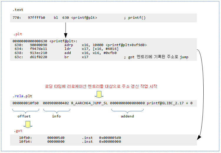
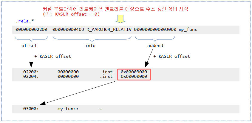
다음 그림은 링크 타임과 로드 타임에 .rela.* 섹션에 위치한 리로케이션 엔트리를 사용하여 주소 갱신을 수행하는 모습을 보여준다.


리로케이션 엔트리 구조

ELF32 규격의 경우 12 바이트 엔트리를 사용한다.

glibc/elf/elf.h – ELF32

typedef struct {
        Elf32_Addr r_offset;
        uint32_t   r_info;
        int32_t    r_addend;
} Elf32_Rela;
  • r_offset
    • 리로케이션할 offset 주소를 담는다.
  • r_info
    • 상위 3 바이트에 심볼 인덱스와 하위 1 바이트에 리로케이션 타입을 담는다.
    • 심볼 인덱스가 0인 경우 null 인덱스라고 한다.
  • r_addend
    • 리로케이션 타입에 따라 수행시 추가되어야 할 값을 담는다.


32비트 ELF 파일의 경우 4 바이트의 info 필드에서 상위 3 바이트를 심볼 인덱스가 사용하고, 나머지 하위 1 바이트를 타입으로 사용한다.


ELF64 규격의 경우 24 바이트 엔트리를 사용한다.

glibc/elf/elf.h – ELF64

typedef struct {
        Elf64_Addr r_offset;
        uint64_t   r_info;
        int64_t    r_addend;
} Elf64_Rela;
  • r_offset
    • 리로케이션할 offset 주소를 담는다.
  • r_info
    • 상위 4 바이트에 심볼 인덱스와 하위 4 바이트에 리로케이션 타입을 담는다.
    • 심볼 인덱스가 0인 경우 null 인덱스라고 한다.
  • r_addend
    • 리로케이션 타입에 따라 수행시 추가되어야 할 값을 담는다.


64비트 ELF 파일의 경우 8 바이트의 info 필드에서 상위 4 바이트를 심볼 인덱스가 사용하고, 나머지 하위 4 바이트를 타입으로 사용한다.


C 언어 데이타 타입 모델

GCC 및 Linux는 C 언어 데이터 타입 모델에서 64 비트 시스템은 LP64 모델을 사용하고, 32 비트 시스템은 ILP32를 사용한다.


리로케이션 기호 표기법

리로케이션 동작에 대한 기호 표시는 다음과 같다.

  • S
    • 심볼 주소
  • A
    • Addend 값
  • P
    • 리로케이트될 장소의 주소
  • X
    • 리로케이션 동작의 결과
  • Page(expr)
    • 페이지 단위의 주소로 하위 12비트가 0으로 클리어된다.
  • GOT
    • Global Offset Table로 다이나믹 링크(로드) 타임에 갱신된다.
  • GDAT(S+A)
    • GOT 내 64비트 엔트리가 S+A 로 동작한다.
  • G(expr)
    • GOT 내 64비트 엔트리 주소
  • Delta(S)
    • 스태틱 링크 타임에 결정된 프로그램 시작 주소와 실행 타임에 변경된 프로그램 시작 주소의 차이(Delta)를 기존 심볼 주소에 더해 반영한다.
      • S + delta
  • _NC
    • None Checking 리로케이션 타입으로 오버플로우 체크를 수행하지 않는다.


리로케이션 타입

ELF format for AArch64에서 사용하는 리로케이션 엔트리 타입들 다음과 같이 많은 종류가 있다.

glibc/elf/elf.h

/* ILP32 AArch64 relocs.  */
#define R_AARCH64_P32_ABS32                      1 /* Direct 32 bit.  */
#define R_AARCH64_P32_COPY                     180 /* Copy symbol at runtime.  */
#define R_AARCH64_P32_GLOB_DAT                 181 /* Create GOT entry.  */
#define R_AARCH64_P32_JUMP_SLOT                182 /* Create PLT entry.  */
#define R_AARCH64_P32_RELATIVE                 183 /* Adjust by program base.  */
#define R_AARCH64_P32_TLS_DTPMOD               184 /* Module number, 32 bit.  */
#define R_AARCH64_P32_TLS_DTPREL               185 /* Module-relative offset, 32 bit.  */
#define R_AARCH64_P32_TLS_TPREL                186 /* TP-relative offset, 32 bit.  */
#define R_AARCH64_P32_TLSDESC                  187 /* TLS Descriptor.  */
#define R_AARCH64_P32_IRELATIVE                188 /* STT_GNU_IFUNC relocation. */


/* LP64 AArch64 relocs.   */
/* 1. Static Data relocs. */
#define R_AARCH64_ABS64                        257 /* Direct 64 bit. */
#define R_AARCH64_ABS32                        258 /* Direct 32 bit.  */
#define R_AARCH64_ABS16                        259 /* Direct 16-bit.  */
#define R_AARCH64_PREL64                       260 /* PC-relative 64-bit.  */
#define R_AARCH64_PREL32                       261 /* PC-relative 32-bit.  */
#define R_AARCH64_PREL16                       262 /* PC-relative 16-bit.  */
#define R_AARCH64_MOVW_UABS_G0                 263 /* Dir. MOVZ imm. from bits 15:0.  */햬

GOT-relative 데이터 리로케이션 타입들이다.

  •  R_AARCH64_ABS64
    • 데이터 리로케이션 타입으로 S + A와 같이 동작한다.
  • R_AARCH64_ABS32
    • 데이터 리로케이션 타입으로 S + A와 같이 동작한다. 단 2^32 범위 내에서 사용되어야 한다.
  • R_AARCH64_PREL32
    • 데이터 리로케이션 타입으로 S + A – P와 같이 동작한다. 단 2^32 범위 내에서 사용되어야 한다.


/* 2. Static AArch64 relocs. */
/* 1) Group relocations to create a 16-, 32-, 48-, or 64-bit unsigned data value or address inline */
#define R_AARCH64_MOVW_UABS_G0_NC              264 /* Likewise for MOVK; no check.  */
#define R_AARCH64_MOVW_UABS_G1                 265 /* Dir. MOVZ imm. from bits 31:16.  */
#define R_AARCH64_MOVW_UABS_G1_NC              266 /* Likewise for MOVK; no check.  */
#define R_AARCH64_MOVW_UABS_G2                 267 /* Dir. MOVZ imm. from bits 47:32.  */
#define R_AARCH64_MOVW_UABS_G2_NC              268 /* Likewise for MOVK; no check.  */
#define R_AARCH64_MOVW_UABS_G3                 269 /* Dir. MOV{K,Z} imm. from 63:48.  */


/* 2) Group relocations to create a 16, 32, 48, or 64 bit signed data or offset value inline */
#define R_AARCH64_MOVW_SABS_G0                 270 /* Dir. MOV{N,Z} imm. from 15:0. */
#define R_AARCH64_MOVW_SABS_G1                 271 /* Dir. MOV{N,Z} imm. from 31:16.  */
#define R_AARCH64_MOVW_SABS_G2                 272 /* Dir. MOV{N,Z} imm. from 47:32.  */


/* 3) Relocations to generate 19, 21 and 33 bit PC-relative addresses */
#define R_AARCH64_LD_PREL_LO19                 273 /* PC-rel. LD imm. from bits 20:2.  */
#define R_AARCH64_ADR_PREL_LO21                274 /* PC-rel. ADR imm. from bits 20:0.  */
#define R_AARCH64_ADR_PREL_PG_HI21             275 /* Page-rel. ADRP imm. from 32:12.  */
#define R_AARCH64_ADR_PREL_PG_HI21_NC          276 /* Likewise; no overflow check.  */
#define R_AARCH64_ADD_ABS_LO12_NC              277 /* Dir. ADD imm. from bits 11:0.  */
#define R_AARCH64_LDST8_ABS_LO12_NC            278 /* Likewise for LD/ST; no check. */
  • R_AARCH64_ADR_PREL_PG_HI21
    • Page(S + A) – Page(P)
    • ADRP 명령을 사용하여 4K 페이지 단위의 PC 기반 relative offset 주소(범위는 +-4GB)를 참조한다. 이 값을 4K로 나누어 hi21 필드에 사용한다.
      • 예) adrp x0, var1
      • C 예) value = *ptr; object 파일 내부의 포인터 변수 참조
  • R_AARCH64_ADD_ABS_LO12_NC
    • S + A
    • ADD 명령을 사용하여 PC 기반 relative offset 주소의 하위 12비트 절대 주소를 참조한다. 이 값은 lo12 필드에 사용한다.
      • 예) add x0, var1
      • C 예) value = *ptr; object 파일 내부의 포인터 변수 참조


/* 4) Relocations for control-flow instructions - all offsets are a multiple of 4 */
#define R_AARCH64_TSTBR14                      279 /* PC-rel. TBZ/TBNZ imm. from 15:2.  */
#define R_AARCH64_CONDBR19                     280 /* PC-rel. cond. br. imm. from 20:2. */
#define R_AARCH64_JUMP26                       282 /* PC-rel. B imm. from bits 27:2.  */
#define R_AARCH64_CALL26                       283 /* Likewise for CALL.  */
  • R_AARCH64_JUMP26
    • S + A – P
      • PC + relative offset 주소(범위는 +-128MB)를 참조한다. 이 값을 4로 나누어 imm26 필드에 사용한다.
  • R_AARCH64_CALL26
    • PC + relative offset 주소(범위는 +-128MB)를 참조한다. 이 값을 4로 나누어 imm26 필드에 사용한다.
      • 예) bl sub1     <- .globl 선언 함수
      • C 예) sub1(); <- static 선언하지 않은 함수


/* 3)에 포함 */
#define R_AARCH64_LDST16_ABS_LO12_NC           284 /* Dir. ADD imm. from bits 11:1.  */
#define R_AARCH64_LDST32_ABS_LO12_NC           285 /* Likewise for bits 11:2.  */
#define R_AARCH64_LDST64_ABS_LO12_NC           286 /* Likewise for bits 11:3.  */
  • R_AARCH64_LDST64_ABS_LO12_NC
    • S + A
    • 주소를 LD/ST 명령의 상수 값을 imm9 필드에 사용한다.


/* 5) Group relocations to create a 16, 32, 48, or 64 bit PC-relative offset inline */
#define R_AARCH64_MOVW_PREL_G0                 287 /* PC-rel. MOV{N,Z} imm. from 15:0.  */
#define R_AARCH64_MOVW_PREL_G0_NC              288 /* Likewise for MOVK; no check.  */
#define R_AARCH64_MOVW_PREL_G1                 289 /* PC-rel. MOV{N,Z} imm. from 31:16. */
#define R_AARCH64_MOVW_PREL_G1_NC              290 /* Likewise for MOVK; no check.  */
#define R_AARCH64_MOVW_PREL_G2                 291 /* PC-rel. MOV{N,Z} imm. from 47:32. */
#define R_AARCH64_MOVW_PREL_G2_NC              292 /* Likewise for MOVK; no check.  */
#define R_AARCH64_MOVW_PREL_G3                 293 /* PC-rel. MOV{N,Z} imm. from 63:48. */
#define R_AARCH64_LDST128_ABS_LO12_NC          299 /* Dir. ADD imm. from bits 11:4. */ 


/* 6) Group relocations to create a 16, 32, 48, or 64 bit GOT-relative offsets inline */
#define R_AARCH64_MOVW_GOTOFF_G0               300 /* GOT-rel. off. MOV{N,Z} imm. 15:0. */
#define R_AARCH64_MOVW_GOTOFF_G0_NC            301 /* Likewise for MOVK; no check.  */
#define R_AARCH64_MOVW_GOTOFF_G1               302 /* GOT-rel. o. MOV{N,Z} imm. 31:16.  */
#define R_AARCH64_MOVW_GOTOFF_G1_NC            303 /* Likewise for MOVK; no check.  */
#define R_AARCH64_MOVW_GOTOFF_G2               304 /* GOT-rel. o. MOV{N,Z} imm. 47:32.  */
#define R_AARCH64_MOVW_GOTOFF_G2_NC            305 /* Likewise for MOVK; no check.  */
#define R_AARCH64_MOVW_GOTOFF_G3               306 /* GOT-rel. o. MOV{N,Z} imm. 63:48. */


/* 7) GOT-relative data relocations */
#define R_AARCH64_GOTREL64                     307 /* GOT-relative 64-bit.  */
#define R_AARCH64_GOTREL32                     308 /* GOT-relative 32-bit. */


/* 8) GOT-relative instruction relocations */
#define R_AARCH64_GOT_LD_PREL19                309 /* PC-rel. GOT off. load imm. 20:2.  */
#define R_AARCH64_LD64_GOTOFF_LO15             310 /* GOT-rel. off. LD/ST imm. 14:3.  */
#define R_AARCH64_ADR_GOT_PAGE                 311 /* P-page-rel. GOT off. ADRP 32:12.  */
#define R_AARCH64_LD64_GOT_LO12_NC             312 /* Dir. GOT off. LD/ST imm. 11:3.  */
#define R_AARCH64_LD64_GOTPAGE_LO15            313 /* GOT-page-rel. GOT off. LD/ST 14:3 */
  • R_AARCH64_ADR_GOT_PAGE
    • Page(G(GDAT(S + A))) – Page(P)
    • 오브젝트 파일 외부 주소를 참조하기 위해 GOT 엔트리에 대해 R_AARCH64_ADR_PREL_PG_HI21 타입과 동일하게 동작한다.
      • 예0 adrp x0, var2 (extern)
      • C 예) value = *ptr; (extern)
  • R_AARCH64_LD64_GOT_LO12_NC
    • G(GDAT(S + A))
    • 오브젝트 파일 외부 주소를 참조하기 위해 GOT 엔트리에 대해 R_AARCH64_ADD_ABS_LO12_NC타입과 동일하게 동작한다.
      • 예) add x0, var1 (extern)
      • C 예) value = *ptr; (extern)


/* 3. Relocations for thread-local storage */
/* 1) General Dynamic TLS relocations      */
#define R_AARCH64_TLSGD_ADR_PREL21             512 /* PC-relative ADR imm. 20:0.  */
#define R_AARCH64_TLSGD_ADR_PAGE21             513 /* page-rel. ADRP imm. 32:12.  */
#define R_AARCH64_TLSGD_ADD_LO12_NC            514 /* direct ADD imm. from 11:0.  */
#define R_AARCH64_TLSGD_MOVW_G1                515 /* GOT-rel. MOV{N,Z} 31:16.  */
#define R_AARCH64_TLSGD_MOVW_G0_NC             516 /* GOT-rel. MOVK imm. 15:0.  */


/* 2) Local Dynamic TLS relocations */
#define R_AARCH64_TLSLD_ADR_PREL21             517 /* Like 512; local dynamic model.  */
#define R_AARCH64_TLSLD_ADR_PAGE21             518 /* Like 513; local dynamic model.  */
#define R_AARCH64_TLSLD_ADD_LO12_NC            519 /* Like 514; local dynamic model.  */
#define R_AARCH64_TLSLD_MOVW_G1                520 /* Like 515; local dynamic model.  */
#define R_AARCH64_TLSLD_MOVW_G0_NC             521 /* Like 516; local dynamic model.  */
#define R_AARCH64_TLSLD_LD_PREL19              522 /* TLS PC-rel. load imm. 20:2.  */
#define R_AARCH64_TLSLD_MOVW_DTPREL_G2         523 /* TLS DTP-rel. MOV{N,Z} 47:32.  */
#define R_AARCH64_TLSLD_MOVW_DTPREL_G1         524 /* TLS DTP-rel. MOV{N,Z} 31:16.  */
#define R_AARCH64_TLSLD_MOVW_DTPREL_G1_NC      525 /* Likewise; MOVK; no check.  */
#define R_AARCH64_TLSLD_MOVW_DTPREL_G0         526 /* TLS DTP-rel. MOV{N,Z} 15:0.  */
#define R_AARCH64_TLSLD_MOVW_DTPREL_G0_NC      527 /* Likewise; MOVK; no check.  */
#define R_AARCH64_TLSLD_ADD_DTPREL_HI12        528 /* DTP-rel. ADD imm. from 23:12. */
#define R_AARCH64_TLSLD_ADD_DTPREL_LO12        529 /* DTP-rel. ADD imm. from 11:0.  */
#define R_AARCH64_TLSLD_ADD_DTPREL_LO12_NC     530 /* Likewise; no ovfl. check.  */
#define R_AARCH64_TLSLD_LDST8_DTPREL_LO12      531 /* DTP-rel. LD/ST imm. 11:0.  */
#define R_AARCH64_TLSLD_LDST8_DTPREL_LO12_NC   532 /* Likewise; no check.  */
#define R_AARCH64_TLSLD_LDST16_DTPREL_LO12     533 /* DTP-rel. LD/ST imm. 11:1.  */
#define R_AARCH64_TLSLD_LDST16_DTPREL_LO12_NC  534 /* Likewise; no check.  */
#define R_AARCH64_TLSLD_LDST32_DTPREL_LO12     535 /* DTP-rel. LD/ST imm. 11:2.  */
#define R_AARCH64_TLSLD_LDST32_DTPREL_LO12_NC  536 /* Likewise; no check.  */
#define R_AARCH64_TLSLD_LDST64_DTPREL_LO12     537 /* DTP-rel. LD/ST imm. 11:3.  */
#define R_AARCH64_TLSLD_LDST64_DTPREL_LO12_NC  538 /* Likewise; no check.  */


/* 3) Initial Exec TLS relocations */
#define R_AARCH64_TLSIE_MOVW_GOTTPREL_G1       539 /* GOT-rel. MOV{N,Z} 31:16.  */
#define R_AARCH64_TLSIE_MOVW_GOTTPREL_G0_NC    540 /* GOT-rel. MOVK 15:0.  */
#define R_AARCH64_TLSIE_ADR_GOTTPREL_PAGE21    541 /* Page-rel. ADRP 32:12.  */
#define R_AARCH64_TLSIE_LD64_GOTTPREL_LO12_NC  542 /* Direct LD off. 11:3.  */
#define R_AARCH64_TLSIE_LD_GOTTPREL_PREL19     543 /* PC-rel. load imm. 20:2.  */


/* 4) Local Exec TLS relocations */ 
#define R_AARCH64_TLSLE_MOVW_TPREL_G2          544 /* TLS TP-rel. MOV{N,Z} 47:32.  */
#define R_AARCH64_TLSLE_MOVW_TPREL_G1          545 /* TLS TP-rel. MOV{N,Z} 31:16.  */
#define R_AARCH64_TLSLE_MOVW_TPREL_G1_NC       546 /* Likewise; MOVK; no check.  */
#define R_AARCH64_TLSLE_MOVW_TPREL_G0          547 /* TLS TP-rel. MOV{N,Z} 15:0.  */
#define R_AARCH64_TLSLE_MOVW_TPREL_G0_NC       548 /* Likewise; MOVK; no check.  */
#define R_AARCH64_TLSLE_ADD_TPREL_HI12         549 /* TP-rel. ADD imm. 23:12.  */
#define R_AARCH64_TLSLE_ADD_TPREL_LO12         550 /* TP-rel. ADD imm. 11:0.  */
#define R_AARCH64_TLSLE_ADD_TPREL_LO12_NC      551 /* Likewise; no ovfl. check.  */
#define R_AARCH64_TLSLE_LDST8_TPREL_LO12       552 /* TP-rel. LD/ST off. 11:0.  */
#define R_AARCH64_TLSLE_LDST8_TPREL_LO12_NC    553 /* Likewise; no ovfl. check. */
#define R_AARCH64_TLSLE_LDST16_TPREL_LO12      554 /* TP-rel. LD/ST off. 11:1.  */
#define R_AARCH64_TLSLE_LDST16_TPREL_LO12_NC   555 /* Likewise; no check.  */
#define R_AARCH64_TLSLE_LDST32_TPREL_LO12      556 /* TP-rel. LD/ST off. 11:2.  */
#define R_AARCH64_TLSLE_LDST32_TPREL_LO12_NC   557 /* Likewise; no check.  */
#define R_AARCH64_TLSLE_LDST64_TPREL_LO12      558 /* TP-rel. LD/ST off. 11:3.  */
#define R_AARCH64_TLSLE_LDST64_TPREL_LO12_NC   559 /* Likewise; no check.  */


/* 5) TLS descriptor relocations */
#define R_AARCH64_TLSDESC_LD_PREL19            560 /* PC-rel. load immediate 20:2.  */
#define R_AARCH64_TLSDESC_ADR_PREL21           561 /* PC-rel. ADR immediate 20:0.  */
#define R_AARCH64_TLSDESC_ADR_PAGE21           562 /* Page-rel. ADRP imm. 32:12.  */
#define R_AARCH64_TLSDESC_LD64_LO12            563 /* Direct LD off. from 11:3.  */
#define R_AARCH64_TLSDESC_ADD_LO12             564 /* Direct ADD imm. from 11:0.  */
#define R_AARCH64_TLSDESC_OFF_G1               565 /* GOT-rel. MOV{N,Z} imm. 31:16.  */
#define R_AARCH64_TLSDESC_OFF_G0_NC            566 /* GOT-rel. MOVK imm. 15:0; no ck.  */
#define R_AARCH64_TLSDESC_LDR                  567 /* Relax LDR.  */
#define R_AARCH64_TLSDESC_ADD                  568 /* Relax ADD.  */
#define R_AARCH64_TLSDESC_CALL                 569 /* Relax BLR.  */


/* 2)에 포함 */
#define R_AARCH64_TLSLE_LDST128_TPREL_LO12     570 /* TP-rel. LD/ST off. 11:4.  */
#define R_AARCH64_TLSLE_LDST128_TPREL_LO12_NC  571 /* Likewise; no check.  */


/* 4)에 포함 */
#define R_AARCH64_TLSLD_LDST128_DTPREL_LO12    572 /* DTP-rel. LD/ST imm. 11:4. */
#define R_AARCH64_TLSLD_LDST128_DTPREL_LO12_NC 573 /* Likewise; no check.  */


/* 4. Dynamic relocs. */
#define R_AARCH64_COPY                        1024 /* Copy symbol at runtime.  */
#define R_AARCH64_GLOB_DAT                    1025 /* Create GOT entry.  */
#define R_AARCH64_JUMP_SLOT                   1026 /* Create PLT entry.  */
#define R_AARCH64_RELATIVE                    1027 /* Adjust by program base.  */
#define R_AARCH64_TLS_DTPMOD                  1028 /* Module number, 64 bit.  */
#define R_AARCH64_TLS_DTPREL                  1029 /* Module-relative offset, 64 bit.  */
#define R_AARCH64_TLS_TPREL                   1030 /* TP-relative offset, 64 bit.  */
#define R_AARCH64_TLSDESC                     1031 /* TLS Descriptor.  */
#define R_AARCH64_IRELATIVE                   1032 /* STT_GNU_IFUNC relocation.  */

런타임에 다이나믹 리로케이션시 사용되는 리로케이션 타입들이다.

  •  R_AARCH64_GLOB_DAT
    • GOT 엔트리를 생성한다.
    • S + A
  • R_AARCH64_JUMP_SLOT
    • PLT 엔트리를 생성한다.
    • S + A
  • R_AARCH64_RELATIVE
    • 스태틱 링크 타임에 결정한 주소와 다이나믹 링크 타임에 결정한 주소가 달라지면 그 차이만큼을 더해서 갱신해야 하는 경우 사용된다.
    • 프로그램 로딩 후 시작 주소가 달라지면 변경되어야 하는 항목에 사용된다.
    • Delta(S) + A
      • = S + Delta + A
    • 리눅스 커널 이미지
      • 보안을 위해 리눅스 커널 이미지가 매핑되는 가상 주소가 랜덤하게 달라질 수 있다. 이러한 경우 커널에서 외부로 export 된 심볼들의 주소들도 바뀌어야 한다. 이들을 지원하기 위해 커널 역시 특별한 리로케이션 엔트리가 준비되어 있다. 이들 타입에 해당하는 모든 주소들을 바뀐 가상 주소 offset을 더해 변경한다.


PLT(Program Linkage Table)

PLT 엔트리는 실행 파일의 바깥쪽 멀리 있는 목적지 주소로 브랜치(long-branch)하기 위한 코드가 구현된다.

  • 일반적으로 목적지의 이름은 알고 있지만, 주소는 모르는 경우 이를 imported symbol이라고 불리운다.
  • PLT 엔트리는 일반적으로 GOT 엔트리로 부터 목적지 주소를 읽어오도록 구현한다.


GOT(Global Object Table)

GOT 엔트리는 다이나믹 링크 타임에 갱신되는 8 바이트 주소가 담긴다.

  • SysV-based Dynamic Shared Objects (DSOs), 즉 공유 라이브러리 함수들에 대한 접근은 프로그램이 로딩되어 다이나믹 링크 타임에 목적지 주소를 알 수 있게된다.


PLT(Program Linkage Table) 및 GOT(Global Object Table) 연동

실행 파일이 로딩되어 다이나믹 링크가 수행될 때 사용할 공유 라이브러리의 심볼 주소를 .got 섹션의 got 테이블에 갱신한다. 이 주소는 실행 코드 -> PLT 엔트리 코드가 -> GOT 엔트리에 있는 주소를 통해 long-branch 할 수 있게 한다.

  • .text 섹션에 위치한 printf() 호출 코드는 bl <label> 형태의 어셈블리 코드를 통해 +-128M 범위내에 위치한 .plt 섹션에 생성된 코드를 호출한다.
  • .plt 섹션에 위치한 코드는 .got 섹션에 있는 8 바이트 주소를 읽어와서 br <Xd> 형태의 어셈블리 코드를 통해 범위 제한 없이 호출할 수 있다.
  • .got 섹션에 위치한 8 바이트 주소는 실행 파일을 로딩하고 다이나믹 링크가 수행될 때 사용할 공유 라이브러리의 심볼 주소로 갱신된다.


Relocatable vs PIC(Position Independent Code)

  • Relocatable
    • 링킹 타임에 스태틱 링킹에 의해 실행 주소 및 각 심볼들에 대한 주소가 결정되어 재배치한다.
    • 로딩 타임에 다이나믹 링킹에 실행 주소의 변경 또는 사용하는 외부 공유 라이브러리의 심볼 주소들에 주소가 결정되어 재배치한다.
  • PIC
    • 링커에 의해 실행된 주소가 의미가 없어 어느 공간에든 위치할 수 있도록 코드를 구성하게 한다.
    • 공유 라이브러리를 빌드하는 경우에도 일반적으로 -fPIC 옵션을 사용하여야 한다.


샘플 C 소스

main.c에서 몇 개의 주소를 참조한다.

  • 내부의 var1 변수 주소를 참조한다.
  • 외부 파일 sub.c에 존재하는 함수 sub1()과 변수 var2 주소를 참조한다.
  • 외부 공유 라이브러리에 있는 출력 함수 printf() 주소를 참조한다.

main.c

#include <stdio.h>

extern int sub1();
extern int var2;

int var1 = 10;
void main()
{
        sub1();
        printf("hello. var1=%d, var2=%d\n", var1, var2);
}


sub.c 파일에서는 아무 조소도 참조하지 않게 하였다.

sub.c

int var2 = 20;

int sub1()
{
        return 1;
}


main.c 파일을 컴파일한 후 main.o 파일의 섹션을 알아본다.

  • 코드 내에서 주소들을 참조하므로 .rela.text 섹션이 생성된 것을 확인할 수 있다.
$ gcc -c main.c
$ readelf -S main.o
There are 11 section headers, starting at offset 0x398:

Section Headers:
  [Nr] Name              Type             Address           Offset
       Size              EntSize          Flags  Link  Info  Align
  [ 0]                   NULL             0000000000000000  00000000
       0000000000000000  0000000000000000           0     0     0
  [ 1] .text             PROGBITS         0000000000000000  00000040
       000000000000003c  0000000000000000  AX       0     0     4
  [ 2] .rela.text        RELA             0000000000000000  00000280
       00000000000000c0  0000000000000018   I       8     1     8
  [ 3] .data             PROGBITS         0000000000000000  0000007c
       0000000000000004  0000000000000000  WA       0     0     4
  [ 4] .bss              NOBITS           0000000000000000  00000080
       0000000000000000  0000000000000000  WA       0     0     1
  [ 5] .rodata           PROGBITS         0000000000000000  00000080
       0000000000000019  0000000000000000   A       0     0     8
  [ 6] .comment          PROGBITS         0000000000000000  00000099
       0000000000000031  0000000000000001  MS       0     0     1
  [ 7] .note.GNU-stack   PROGBITS         0000000000000000  000000ca
       0000000000000000  0000000000000000           0     0     1
  [ 8] .symtab           SYMTAB           0000000000000000  000000d0
       0000000000000180  0000000000000018           9    11     8
  [ 9] .strtab           STRTAB           0000000000000000  00000250
       0000000000000029  0000000000000000           0     0     1
  [10] .shstrtab         STRTAB           0000000000000000  00000340
       0000000000000052  0000000000000000           0     0     1


sub.c 파일을 컴파일한 후 sub.o 파일의 섹션을 알아본다.

  • 코드 내에서 하나의 주소 참조도 없어 .rela.text 섹션이 생성되지 않은 것을 확인할 수 있다.
$ gcc -c main.c
$ readelf -S sub.o
There are 9 section headers, starting at offset 0x1e8:

Section Headers:
  [Nr] Name              Type             Address           Offset
       Size              EntSize          Flags  Link  Info  Align
  [ 0]                   NULL             0000000000000000  00000000
       0000000000000000  0000000000000000           0     0     0
  [ 1] .text             PROGBITS         0000000000000000  00000040
       0000000000000008  0000000000000000  AX       0     0     4
  [ 2] .data             PROGBITS         0000000000000000  00000048
       0000000000000004  0000000000000000  WA       0     0     4
  [ 3] .bss              NOBITS           0000000000000000  0000004c
       0000000000000000  0000000000000000  WA       0     0     1
  [ 4] .comment          PROGBITS         0000000000000000  0000004c
       0000000000000031  0000000000000001  MS       0     0     1
  [ 5] .note.GNU-stack   PROGBITS         0000000000000000  0000007d
       0000000000000000  0000000000000000           0     0     1
  [ 6] .symtab           SYMTAB           0000000000000000  00000080
       0000000000000108  0000000000000018           7     9     8
  [ 7] .strtab           STRTAB           0000000000000000  00000188
       0000000000000017  0000000000000000           0     0     1
  [ 8] .shstrtab         STRTAB           0000000000000000  0000019f
       0000000000000045  0000000000000000           0     0     1


test 실행 파일의 섹션을 알아본다.

  • .rela.dyn 및 .rela.plt 섹션이 생성되었음을 확인한다.
  • 또한 새롭게 추가된 .plt 및 .got 섹션을 확인한다.
$ strip test; readelf -S test
There are 25 section headers, starting at offset 0x1128:

Section Headers:
  [Nr] Name              Type             Address           Offset
       Size              EntSize          Flags  Link  Info  Align
  [ 0]                   NULL             0000000000000000  00000000
       0000000000000000  0000000000000000           0     0     0
  [ 1] .interp           PROGBITS         0000000000000200  00000200
       000000000000001b  0000000000000000   A       0     0     1
  [ 2] .note.ABI-tag     NOTE             000000000000021c  0000021c
       0000000000000020  0000000000000000   A       0     0     4
  [ 3] .note.gnu.build-i NOTE             000000000000023c  0000023c
       0000000000000024  0000000000000000   A       0     0     4
  [ 4] .gnu.hash         GNU_HASH         0000000000000260  00000260
       000000000000001c  0000000000000000   A       5     0     8
  [ 5] .dynsym           DYNSYM           0000000000000280  00000280
       00000000000000f0  0000000000000018   A       6     3     8
  [ 6] .dynstr           STRTAB           0000000000000370  00000370
       0000000000000089  0000000000000000   A       0     0     1
  [ 7] .gnu.version      VERSYM           00000000000003fa  000003fa
       0000000000000014  0000000000000002   A       5     0     2
  [ 8] .gnu.version_r    VERNEED          0000000000000410  00000410
       0000000000000020  0000000000000000   A       6     1     8
  [ 9] .rela.dyn         RELA             0000000000000430  00000430
       0000000000000108  0000000000000018   A       5     0     8
  [10] .rela.plt         RELA             0000000000000538  00000538
       0000000000000078  0000000000000018  AI       5    20     8
  [11] .init             PROGBITS         00000000000005b0  000005b0
       0000000000000014  0000000000000000  AX       0     0     4
  [12] .plt              PROGBITS         00000000000005d0  000005d0
       0000000000000070  0000000000000010  AX       0     0     16
  [13] .text             PROGBITS         0000000000000640  00000640
       00000000000001cc  0000000000000000  AX       0     0     8
  [14] .fini             PROGBITS         000000000000080c  0000080c
       0000000000000010  0000000000000000  AX       0     0     4
  [15] .rodata           PROGBITS         0000000000000820  00000820
       0000000000000021  0000000000000000   A       0     0     8
  [16] .eh_frame         PROGBITS         0000000000000844  00000844
       0000000000000004  0000000000000000   A       0     0     4
  [17] .init_array       INIT_ARRAY       0000000000010d78  00000d78
       0000000000000008  0000000000000008  WA       0     0     8
  [18] .fini_array       FINI_ARRAY       0000000000010d80  00000d80
       0000000000000008  0000000000000008  WA       0     0     8
  [19] .dynamic          DYNAMIC          0000000000010d88  00000d88
       00000000000001f0  0000000000000010  WA       6     0     8
  [20] .got              PROGBITS         0000000000010f78  00000f78
       0000000000000088  0000000000000008  WA       0     0     8
  [21] .data             PROGBITS         0000000000011000  00001000
       0000000000000018  0000000000000000  WA       0     0     8
  [22] .bss              NOBITS           0000000000011018  00001018
       0000000000000008  0000000000000000  WA       0     0     1
  [23] .comment          PROGBITS         0000000000000000  00001018
       0000000000000030  0000000000000001  MS       0     0     1
  [24] .shstrtab         STRTAB           0000000000000000  00001048
       00000000000000dc  0000000000000000           0     0     1


리로케이션 덤프 분석


main.o 파일에 대한 디스어셈블 코드

아래 주황색 및 파란색 부분은 주소를 참조하는 부분이며 링커를 사용하지 않은 상태이므로 엔코딩된 명령문에서 주소에 관련된 필드가 0인 상태로 아직 완성되지 않았다.

$ objdump -d -D main.o

main.o:     file format elf64-littleaarch64

Disassembly of section .text:

0000000000000000 <main>:
   0:   a9bf7bfd        stp     x29, x30, [sp, #-16]!
   4:   910003fd        mov     x29, sp
   8:   94000000        bl      0 <sub1>           ; sub1() 호출
   c:   90000000        adrp    x0, 0 <main>       ; va1 값
  10:   91000000        add     x0, x0, #0x0
  14:   b9400001        ldr     w1, [x0]
  18:   90000000        adrp    x0, 0 <var2>       ; var2 값
  1c:   f9400000        ldr     x0, [x0]
  20:   b9400002        ldr     w2, [x0]
  24:   90000000        adrp    x0, 0 <main>       ; const 문자열
  28:   91000000        add     x0, x0, #0x0
  2c:   94000000        bl      0 <printf>         ; printf() 호출
  30:   d503201f        nop
  34:   a8c17bfd        ldp     x29, x30, [sp], #16
  38:   d65f03c0        ret

Disassembly of section .data:

0000000000000000 <var1>:
   0:   0000000a        .word   0x0000000a

Disassembly of section .rodata:


main.o 파일의 리로케이션 엔트리

.text 섹션내에서 총 8개의 리로케이션 엔트리가 사용됨을 알 수 있다. 이들은 링크 타임에서 주소 갱신을 위해 활용된다.

  • .rodata 영역에는 const 문자열이 포함되어 있다.
$ objdump -r main.o

main.o:     file format elf64-littleaarch64

RELOCATION RECORDS FOR [.text]:
OFFSET           TYPE                           VALUE
0000000000000008 R_AARCH64_CALL26               sub1
000000000000000c R_AARCH64_ADR_PREL_PG_HI21     var1
0000000000000010 R_AARCH64_ADD_ABS_LO12_NC      var1
0000000000000018 R_AARCH64_ADR_GOT_PAGE         var2
000000000000001c R_AARCH64_LD64_GOT_LO12_NC     var2
0000000000000024 R_AARCH64_ADR_PREL_PG_HI21     .rodata
0000000000000028 R_AARCH64_ADD_ABS_LO12_NC      .rodata
000000000000002c R_AARCH64_CALL26               printf


test 실행 파일의 리로케이션 엔트리

.rela.dyn 및 .rela.plt 섹션에서 총 16개의 주소 참조가 발생하였다.

  • 이 엔트리들은 런타임에 외부 공유 라이브러리 등과 연결될 때 주소 갱신을 위해 사용된다.
$ gcc main.c sub.c; strip test; readelf -r test

Relocation section '.rela.dyn' at offset 0x430 contains 11 entries:
  Offset          Info           Type           Sym. Value    Sym. Name + Addend
000000010d78  000000000403 R_AARCH64_RELATIV                    740
000000010d80  000000000403 R_AARCH64_RELATIV                    6f8
000000010fc0  000000000403 R_AARCH64_RELATIV                    808
000000010fd0  000000000403 R_AARCH64_RELATIV                    11014
000000010fe8  000000000403 R_AARCH64_RELATIV                    788
000000010ff0  000000000403 R_AARCH64_RELATIV                    744
000000011008  000000000403 R_AARCH64_RELATIV                    11008
000000010fc8  000300000401 R_AARCH64_GLOB_DA 0000000000000000 _ITM_deregisterTMClone + 0
000000010fd8  000400000401 R_AARCH64_GLOB_DA 0000000000000000 __cxa_finalize@GLIBC_2.17 + 0
000000010fe0  000600000401 R_AARCH64_GLOB_DA 0000000000000000 __gmon_start__ + 0
000000010ff8  000800000401 R_AARCH64_GLOB_DA 0000000000000000 _ITM_registerTMCloneTa + 0

Relocation section '.rela.plt' at offset 0x538 contains 5 entries:
  Offset          Info           Type           Sym. Value    Sym. Name + Addend
000000010f90  000400000402 R_AARCH64_JUMP_SL 0000000000000000 __cxa_finalize@GLIBC_2.17 + 0
000000010f98  000500000402 R_AARCH64_JUMP_SL 0000000000000000 __libc_start_main@GLIBC_2.17 + 0
000000010fa0  000600000402 R_AARCH64_JUMP_SL 0000000000000000 __gmon_start__ + 0
000000010fa8  000700000402 R_AARCH64_JUMP_SL 0000000000000000 abort@GLIBC_2.17 + 0
000000010fb0  000900000402 R_AARCH64_JUMP_SL 0000000000000000 printf@GLIBC_2.17 + 0


main 실행 파일 로드 전의 디스어셈블 코드

아래 파란색상의 글씨는 링크 프로세스를 수행한 후에 갱신된 부분이다.

Disassembly of section .text:

0000000000000744 <main>:
 744:   a9bf7bfd        stp     x29, x30, [sp, #-16]!
 748:   910003fd        mov     x29, sp
 74c:   9400000d        bl      780 <sub1>                         ; R_AARCH64_CALL26               sub1
 750:   b0000080        adrp    x0, 11000 <__data_start>           ; R_AARCH64_ADR_PREL_PG_HI21     var1
 754:   91004000        add     x0, x0, #0x10                      ; R_AARCH64_ADD_ABS_LO12_NC      var1
 758:   b9400001        ldr     w1, [x0]
 75c:   90000080        adrp    x0, 10000 <__FRAME_END__+0xf7bc>   ; R_AARCH64_ADR_GOT_PAGE         var2
 760:   f947e800        ldr     x0, [x0, #4048]                    ; R_AARCH64_LD64_GOT_LO12_NC     var2
 764:   b9400002        ldr     w2, [x0]
 768:   90000000        adrp    x0, 0 <_init-0x5b0>                ; R_AARCH64_ADR_PREL_PG_HI21     .rodata
 76c:   9120a000        add     x0, x0, #0x828                     ; R_AARCH64_ADD_ABS_LO12_NC      .rodata
 770:   97ffffb0        bl      630 <printf@plt>                   ; R_AARCH64_CALL26               printf
 774:   d503201f        nop
 778:   a8c17bfd        ldp     x29, x30, [sp], #16
 77c:   d65f03c0        ret


다음 .plt 섹션에는 런타임에 외부 공유 라이브러리와의 연결에 사용되는 .got 섹션의 엔트리들을 가리키도록 코드가 생성된다.

  • 실행파일내의 모든 printf() 호출 부분은 printf@plt 레이블에 생성된 코드를 통한다.
$ objdump -d -D test
Disassembly of section .plt:

(...생략...)

0000000000000620 <abort@plt>:
(...생략...)

0000000000000630 <printf@plt>:
 630:   90000090        adrp    x16, 10000 <printf@plt+0xf9d0>
 634:   f947da11        ldr     x17, [x16, #4016]
 638:   913ec210        add     x16, x16, #0xfb0
 63c:   d61f0220        br      x17

외부 공유 라이브러리에 존재하는 printf() 함수를 호출한다.

  • .got 섹션에 있는 .got 엔트리중 0x10fb0 offset 주소에 담긴 외부 printf() 주소를 x17에 알아온 후 이 루틴을 호출한다.


다음 .got 섹션에는 외부 공유 라이브러리와 함수 또는 변수의 절대 주소를 담고 있다.

  • 아래 값은 실행파일이 로드될 때 주 메모리에서만 엔트리가 갱신된다.
Disassembly of section .got:

0000000000010f78 <.got>:
        ...
   10fb0:       000005d0        .inst   0x000005d0 ; undefined
   10fb4:       00000000        .inst   0x00000000 ; undefined


main 실행 파일 로드 후의 디스어셈블 코드

다음은 실행 파일을 로드한 후 동작하기 직전의 디스어셈블 코드이다.

  • 모든 offset 로드된 가상 주소로 변경되었다.
  • got 엔트리의 printf() 함수에 대한 주소가 0x7ff7ec49a0로 변경되어 있음을 알 수 있다.
Disassembly of section .plt:

0x0000005555555630 <printf@plt>:
   0x0000005555555630 <+0>:     adrp    x16, 0x5555565000
   0x0000005555555634 <+4>:     ldr     x17, [x16, #4016]
   0x0000005555555638 <+8>:     add     x16, x16, #0xfb0
   0x000000555555563c <+12>:    br      x17


Disassembly of section .text:

0x0000005555555744 <main>:
   0x0000005555555744 <+0>:     stp     x29, x30, [sp, #-16]!
   0x0000005555555748 <+4>:     mov     x29, sp
   0x000000555555574c <+8>:     bl      0x5555555780 <sub1>
   0x0000005555555750 <+12>:    adrp    x0, 0x5555566000
   0x0000005555555754 <+16>:    add     x0, x0, #0x10
   0x0000005555555758 <+20>:    ldr     w1, [x0]
   0x000000555555575c <+24>:    adrp    x0, 0x5555565000
   0x0000005555555760 <+28>:    ldr     x0, [x0, #4048]
   0x0000005555555764 <+32>:    ldr     w2, [x0]
   0x0000005555555768 <+36>:    adrp    x0, 0x5555555000
   0x000000555555576c <+40>:    add     x0, x0, #0x828
   0x0000005555555770 <+44>:    bl      0x5555555630 <printf@plt>
   0x0000005555555774 <+48>:    nop
   0x0000005555555778 <+52>:    ldp     x29, x30, [sp], #16
   0x000000555555577c <+56>:    ret


Disassembly of section .got:

0x0000005555565f78 <.got>:
        ...
   0x0000005555565fb0:       0xf7ec49a0        .inst   0xf7ec49a0  
   0x0000005555565fb8:       0x0000007f        .inst   0x0000007f 
        ...


head.o 주소 참조부 ELF 분석


다음은 커널의 어셈블리 파트 시작을 담당하는 head.S를 어셈블한 파일의 섹션들을 살펴본다.

$ readelf -S head.o
There are 29 section headers, starting at offset 0x22350:

Section Headers:
  [Nr] Name              Type             Address           Offset
       Size              EntSize          Flags  Link  Info  Align
  [ 0]                   NULL             0000000000000000  00000000
       0000000000000000  0000000000000000           0     0     0
  [ 1] .text             PROGBITS         0000000000000000  00000040
       0000000000000000  0000000000000000  AX       0     0     1
  [ 2] .data             PROGBITS         0000000000000000  00000040
       0000000000000000  0000000000000000  WA       0     0     1
  [ 3] .bss              NOBITS           0000000000000000  00000040
       0000000000000000  0000000000000000  WA       0     0     1
  [ 4] .head.text        PROGBITS         0000000000000000  00010000
       0000000000010000  0000000000000000  AX       0     0     65536
  [ 5] .rela.head.text   RELA             0000000000000000  00021720
       0000000000000180  0000000000000018   I      26     4     8
  [ 6] .init.text        PROGBITS         0000000000000000  00020000
       00000000000003a8  0000000000000000  AX       0     0     4
  [ 7] .rela.init.text   RELA             0000000000000000  000218a0
       00000000000004e0  0000000000000018   I      26     6     8
  [ 8] .rodata           PROGBITS         0000000000000000  000203a8
       0000000000000008  0000000000000000   A       0     0     1
  [ 9] .rela.rodata      RELA             0000000000000000  00021d80
       0000000000000018  0000000000000018   I      26     8     8
  [10] ___ksymtab+kimage PROGBITS         0000000000000000  000203b0
       000000000000000c  0000000000000000   A       0     0     4
  [11] .rela___ksymtab+k RELA             0000000000000000  00021d98
       0000000000000030  0000000000000018   I      26    10     8
  [12] __ksymtab_strings PROGBITS         0000000000000000  000203bc
       000000000000000d  0000000000000001 AMS       0     0     1
  [13] .idmap.text       PROGBITS         0000000000000000  000203d0
       0000000000000340  0000000000000000 WAX       0     0     8
  [14] .rela.idmap.text  RELA             0000000000000000  00021dc8
       00000000000002b8  0000000000000018   I      26    13     8
  [15] .mmuoff.data.writ PROGBITS         0000000000000000  00020710
       0000000000000010  0000000000000000  WA       0     0     1
  [16] .debug_line       PROGBITS         0000000000000000  00020720
       000000000000019b  0000000000000000           0     0     1
  [17] .rela.debug_line  RELA             0000000000000000  00022080
       0000000000000048  0000000000000018   I      26    16     8
  [18] .debug_info       PROGBITS         0000000000000000  000208bb
       0000000000000022  0000000000000000           0     0     1
  [19] .rela.debug_info  RELA             0000000000000000  000220c8
       0000000000000090  0000000000000018   I      26    18     8
  [20] .debug_abbrev     PROGBITS         0000000000000000  000208dd
       0000000000000012  0000000000000000           0     0     1
  [21] .debug_aranges    PROGBITS         0000000000000000  000208f0
       0000000000000050  0000000000000000           0     0     16
  [22] .rela.debug_arang RELA             0000000000000000  00022158
       0000000000000060  0000000000000018   I      26    21     8
  [23] .debug_str        PROGBITS         0000000000000000  00020940
       0000000000000040  0000000000000001  MS       0     0     1
  [24] .debug_ranges     PROGBITS         0000000000000000  00020980
       0000000000000050  0000000000000000           0     0     16
  [25] .rela.debug_range RELA             0000000000000000  000221b8
       0000000000000090  0000000000000018   I      26    24     8
  [26] .symtab           SYMTAB           0000000000000000  000209d0
       0000000000000900  0000000000000018          27    48     8
  [27] .strtab           STRTAB           0000000000000000  000212d0
       0000000000000450  0000000000000000           0     0     1
  [28] .shstrtab         STRTAB           0000000000000000  00022248
       0000000000000108  0000000000000000           0     0     1
Key to Flags:
  W (write), A (alloc), X (execute), M (merge), S (strings), I (info),
  L (link order), O (extra OS processing required), G (group), T (TLS),
  C (compressed), x (unknown), o (OS specific), E (exclude),
  p (processor specific)


head.S에서 주소 참조된 엔트리들을 살펴본다.

$ objdump -r head.o

head.o:     file format elf64-littleaarch64

RELOCATION RECORDS FOR [.head.text]:
OFFSET           TYPE              VALUE
0000000000000004 R_AARCH64_JUMP26  primary_entry
0000000000000010 R_AARCH64_ABS32   _kernel_size_le_lo32
0000000000000014 R_AARCH64_ABS32   _kernel_size_le_hi32
0000000000000018 R_AARCH64_ABS32   _kernel_flags_le_lo32
000000000000001c R_AARCH64_ABS32   _kernel_flags_le_hi32
000000000000005c R_AARCH64_PREL32  __initdata_begin-0x000000000000ffa4
0000000000000060 R_AARCH64_ABS32   __pecoff_data_size
0000000000000068 R_AARCH64_PREL32  __efistub_efi_pe_entry+0x0000000000000068
000000000000007c R_AARCH64_ABS32   PECOFF_FILE_ALIGNMENT
0000000000000090 R_AARCH64_PREL32  _end+0x0000000000000090
0000000000000100 R_AARCH64_PREL32  __initdata_begin-0x000000000000ff00
0000000000000108 R_AARCH64_PREL32  __initdata_begin-0x000000000000fef8
0000000000000128 R_AARCH64_ABS32   __pecoff_data_size
000000000000012c R_AARCH64_PREL32  __initdata_begin+0x000000000000012c
0000000000000130 R_AARCH64_ABS32   __pecoff_data_rawsize
0000000000000134 R_AARCH64_PREL32  __initdata_begin+0x0000000000000134


RELOCATION RECORDS FOR [.init.text]:
OFFSET           TYPE              VALUE
0000000000000004 R_AARCH64_CALL26  el2_setup
0000000000000008 R_AARCH64_ADR_PREL_PG_HI21  _text
0000000000000010 R_AARCH64_CALL26  .idmap.text+0x0000000000000180
0000000000000018 R_AARCH64_CALL26  __cpu_setup
000000000000001c R_AARCH64_JUMP26  .idmap.text+0x0000000000000310
0000000000000024 R_AARCH64_ADR_PREL_PG_HI21  boot_args
0000000000000028 R_AARCH64_ADD_ABS_LO12_NC  boot_args
000000000000003c R_AARCH64_JUMP26  __inval_dcache_area
0000000000000044 R_AARCH64_ADR_PREL_PG_HI21  init_pg_dir
0000000000000048 R_AARCH64_ADR_PREL_PG_HI21  init_pg_end
0000000000000050 R_AARCH64_CALL26  __inval_dcache_area
0000000000000054 R_AARCH64_ADR_PREL_PG_HI21  init_pg_dir
0000000000000058 R_AARCH64_ADR_PREL_PG_HI21  init_pg_end
000000000000007c R_AARCH64_ADR_PREL_PG_HI21  idmap_pg_dir
0000000000000080 R_AARCH64_ADR_PREL_PG_HI21  __idmap_text_start
0000000000000088 R_AARCH64_ADR_PREL_PG_HI21  vabits_actual
000000000000008c R_AARCH64_ADD_ABS_LO12_NC  vabits_actual
000000000000009c R_AARCH64_ADR_PREL_PG_HI21  __idmap_text_end
00000000000000ac R_AARCH64_ADR_PREL_PG_HI21  idmap_t0sz
00000000000000b0 R_AARCH64_ADD_ABS_LO12_NC  idmap_t0sz
00000000000000c4 R_AARCH64_ADR_PREL_PG_HI21  idmap_ptrs_per_pgd
00000000000000c8 R_AARCH64_LDST64_ABS_LO12_NC  idmap_ptrs_per_pgd
00000000000000cc R_AARCH64_ADR_PREL_PG_HI21  idmap_ptrs_per_pgd
00000000000000d0 R_AARCH64_LDST64_ABS_LO12_NC  idmap_ptrs_per_pgd
00000000000000d8 R_AARCH64_ADR_PREL_PG_HI21  __idmap_text_end
00000000000000dc R_AARCH64_ADD_ABS_LO12_NC  __idmap_text_end
00000000000001e0 R_AARCH64_ADR_PREL_PG_HI21  init_pg_dir
00000000000001f8 R_AARCH64_ADR_PREL_PG_HI21  _end
00000000000001fc R_AARCH64_ADR_PREL_PG_HI21  _text
000000000000030c R_AARCH64_ADR_PREL_PG_HI21  idmap_pg_dir
0000000000000310 R_AARCH64_ADR_PREL_PG_HI21  idmap_pg_end
0000000000000318 R_AARCH64_CALL26  __inval_dcache_area
000000000000031c R_AARCH64_ADR_PREL_PG_HI21  init_pg_dir
0000000000000320 R_AARCH64_ADR_PREL_PG_HI21  init_pg_end
0000000000000328 R_AARCH64_CALL26  __inval_dcache_area
0000000000000330 R_AARCH64_ADR_PREL_PG_HI21  init_thread_union
0000000000000338 R_AARCH64_ADR_PREL_PG_HI21  init_task
000000000000033c R_AARCH64_ADD_ABS_LO12_NC  init_task
0000000000000344 R_AARCH64_ADR_PREL_PG_HI21  vectors
0000000000000348 R_AARCH64_ADD_ABS_LO12_NC  vectors
000000000000035c R_AARCH64_ADR_PREL_PG_HI21  __fdt_pointer
0000000000000360 R_AARCH64_LDST64_ABS_LO12_NC  __fdt_pointer
0000000000000364 R_AARCH64_ADR_PREL_PG_HI21  kimage_vaddr
0000000000000368 R_AARCH64_LDST64_ABS_LO12_NC  kimage_vaddr
0000000000000370 R_AARCH64_ADR_PREL_PG_HI21  kimage_voffset
0000000000000374 R_AARCH64_LDST64_ABS_LO12_NC  kimage_voffset
0000000000000378 R_AARCH64_ADR_PREL_PG_HI21  __bss_start
000000000000037c R_AARCH64_ADD_ABS_LO12_NC  __bss_start
0000000000000384 R_AARCH64_ADR_PREL_PG_HI21  __bss_stop
0000000000000388 R_AARCH64_ADD_ABS_LO12_NC  __bss_stop
0000000000000390 R_AARCH64_CALL26  __pi_memset
00000000000003a4 R_AARCH64_JUMP26  start_kernel


RELOCATION RECORDS FOR [.rodata]:
OFFSET           TYPE              VALUE
0000000000000000 R_AARCH64_ABS64   _text


RELOCATION RECORDS FOR [___ksymtab+kimage_vaddr]:
OFFSET           TYPE              VALUE
0000000000000000 R_AARCH64_PREL32  kimage_vaddr
0000000000000004 R_AARCH64_PREL32  __kstrtab_kimage_vaddr


RELOCATION RECORDS FOR [.idmap.text]:
OFFSET           TYPE              VALUE
0000000000000160 R_AARCH64_ADR_PREL_PG_HI21  __hyp_stub_vectors
0000000000000164 R_AARCH64_ADD_ABS_LO12_NC  __hyp_stub_vectors
0000000000000180 R_AARCH64_ADR_PREL_PG_HI21  __boot_cpu_mode
0000000000000184 R_AARCH64_ADD_ABS_LO12_NC  __boot_cpu_mode
00000000000001a4 R_AARCH64_CALL26  el2_setup
00000000000001c0 R_AARCH64_ADR_PREL_PG_HI21  secondary_holding_pen_release
00000000000001c4 R_AARCH64_ADD_ABS_LO12_NC  secondary_holding_pen_release
00000000000001dc R_AARCH64_CALL26  el2_setup
00000000000001e8 R_AARCH64_CALL26  __cpu_secondary_check52bitva
00000000000001ec R_AARCH64_CALL26  __cpu_setup
00000000000001f0 R_AARCH64_ADR_PREL_PG_HI21  swapper_pg_dir
00000000000001f4 R_AARCH64_CALL26  __enable_mmu
0000000000000200 R_AARCH64_ADR_PREL_PG_HI21  vectors
0000000000000204 R_AARCH64_ADD_ABS_LO12_NC  vectors
0000000000000210 R_AARCH64_ADR_PREL_PG_HI21  secondary_data
0000000000000214 R_AARCH64_ADD_ABS_LO12_NC  secondary_data
0000000000000238 R_AARCH64_JUMP26  secondary_start_kernel
000000000000025c R_AARCH64_ADR_PREL_PG_HI21  __early_cpu_boot_status
0000000000000260 R_AARCH64_ADD_ABS_LO12_NC  __early_cpu_boot_status
0000000000000270 R_AARCH64_ADR_PREL_PG_HI21  idmap_pg_dir
00000000000002a8 R_AARCH64_ADR_PREL_PG_HI21  __early_cpu_boot_status
00000000000002ac R_AARCH64_ADD_ABS_LO12_NC  __early_cpu_boot_status
0000000000000310 R_AARCH64_ADR_PREL_PG_HI21  init_pg_dir
0000000000000314 R_AARCH64_CALL26  __enable_mmu
0000000000000320 R_AARCH64_ADR_PREL_PG_HI21  _text
0000000000000328 R_AARCH64_ABS32   __rela_offset
000000000000032c R_AARCH64_ABS32   __rela_size
0000000000000330 R_AARCH64_ABS64   .idmap.text+0x0000000000000200
0000000000000338 R_AARCH64_ABS64   .init.text+0x0000000000000330


RELOCATION RECORDS FOR [.debug_line]:
OFFSET           TYPE              VALUE
000000000000003c R_AARCH64_ABS64   .head.text
0000000000000052 R_AARCH64_ABS64   .init.text
00000000000000d1 R_AARCH64_ABS64   .idmap.text


RELOCATION RECORDS FOR [.debug_info]:
OFFSET           TYPE              VALUE
0000000000000006 R_AARCH64_ABS32   .debug_abbrev
000000000000000c R_AARCH64_ABS32   .debug_line
0000000000000010 R_AARCH64_ABS32   .debug_ranges
0000000000000014 R_AARCH64_ABS32   .debug_str
0000000000000018 R_AARCH64_ABS32   .debug_str+0x0000000000000019
000000000000001c R_AARCH64_ABS32   .debug_str+0x0000000000000034


RELOCATION RECORDS FOR [.debug_aranges]:
OFFSET           TYPE              VALUE
0000000000000006 R_AARCH64_ABS32   .debug_info
0000000000000010 R_AARCH64_ABS64   .head.text
0000000000000020 R_AARCH64_ABS64   .init.text
0000000000000030 R_AARCH64_ABS64   .idmap.text


RELOCATION RECORDS FOR [.debug_ranges]:
OFFSET           TYPE              VALUE
0000000000000010 R_AARCH64_ABS64   .head.text
0000000000000018 R_AARCH64_ABS64   .head.text+0x0000000000010000
0000000000000020 R_AARCH64_ABS64   .init.text
0000000000000028 R_AARCH64_ABS64   .init.text+0x00000000000003a8
0000000000000030 R_AARCH64_ABS64   .idmap.text
0000000000000038 R_AARCH64_ABS64   .idmap.text+0x0000000000000340


ELF64 포맷 분석


간단한 어셈블리 샘플 프로그램 test.S

.text
.globl _start
.align 2

_start:
        adrp x0, msg
        add x0, x0, :lo12:msg   // 어셈블 타임에 msg2 주소의 하위 12비트를 취해 더함.

        adr x1, msg

        ldr x2, msg

        ldr x3, =msg

        /* sys_exit 코드 */
        mov x0, 123
        mov x8, 93
        svc #0

.data

msg:
        .quad 10


위의 test.S를 빌드한 후 hexdump 한 값들을 보여준다.

$ hexdump -S test
[ELF Header]
00000000  7f 45 4c 46 02 01 01 00  00 00 00 00 00 00 00 00  |.ELF............|
00000010  02 00 b7 00 01 00 00 00  b0 00 40 00 00 00 00 00  |..........@.....|
00000020  40 00 00 00 00 00 00 00  58 04 00 00 00 00 00 00  |@.......X.......|
00000030  00 00 00 00 40 00 38 00  02 00 40 00 0b 00 0a 00  |....@.8...@.....|

[Program Header]
[0]
00000040  01 00 00 00 05 00 00 00  00 00 00 00 00 00 00 00  |................|
00000050  00 00 40 00 00 00 00 00  00 00 40 00 00 00 00 00  |..@.......@.....|
00000060  d8 00 00 00 00 00 00 00  d8 00 00 00 00 00 00 00  |................|
00000070  00 00 01 00 00 00 00 00  

[1]
				   01 00 00 00 06 00 00 00  |................|
00000080  d8 00 00 00 00 00 00 00  d8 00 41 00 00 00 00 00  |..........A.....|
00000090  d8 00 41 00 00 00 00 00  04 00 00 00 00 00 00 00  |..A.............|
000000a0  04 00 00 00 00 00 00 00  00 00 01 00 00 00 00 00  |................|

[Section]
[.text: virt=0x4000b0]
000000b0  80 00 00 90 00 60 03 91  01 01 08 10 e2 00 08 58  |.....`.........X|
000000c0  83 00 00 58 60 0f 80 d2  a8 0b 80 d2 01 00 00 d4  |...X`...........|
000000d0  d8 00 41 00 00 00 00 00  

[.data: virt=0x4100d8]
000000d8                           0a 00 00 00 00 00 00 00  |..A.............|

[.debug_arranges]
000000e0  2c 00 00 00 02 00 00 00  00 00 08 00 00 00 00 00  |,...............|
000000f0  b0 00 40 00 00 00 00 00  28 00 00 00 00 00 00 00  |..@.....(.......|
00000100  00 00 00 00 00 00 00 00  00 00 00 00 00 00 00 00  |................|


[.debug_info]
00000110  2a 00 00 00 02 00 00 00  00 00 08 01 00 00 00 00  |*...............|
00000120  b0 00 40 00 00 00 00 00  d8 00 40 00 00 00 00 00  |..@.......@.....|
00000130  00 00 00 00 07 00 00 00  21 00 00 00 01 80 

[.debug_abbrev]
                                                     01 11  |........!.......|
00000140  00 10 06 11 01 12 01 03  0e 1b 0e 25 0e 13 05 00  |...........%....|
00000150  00 00 

[.debug_line]
                3b 00 00 00 02 00  1d 00 00 00 04 01 fb 0e  |..;.............|
00000160  0d 00 01 01 01 01 00 00  00 01 00 00 01 00 74 65  |..............te|
00000170  73 74 2e 53 00 00 00 00  00 00 09 02 b0 00 40 00  |st.S..........@.|
00000180  00 00 00 00 17 21 22 22  22 23 21 21 02 03 00 01  |.....!"""#!!....|
00000190  01 

[.debug_str]
             74 65 73 74 2e 53 00  2f 72 6f 6f 74 2f 77 6f  |.test.S./root/wo|
000001a0  72 6b 73 70 61 63 65 2f  74 65 73 74 2f 61 73 6d  |rkspace/test/asm|
000001b0  35 00 47 4e 55 20 41 53  20 32 2e 33 30 00 

[.symtab]
                                                     00 00  |5.GNU AS 2.30...|
000001c0  00 00 00 00 00 00 00 00  00 00 00 00 00 00 00 00  |................|
000001d0  00 00 00 00 00 00 00 00  00 00 00 00 03 00 01 00  |................|
000001e0  b0 00 40 00 00 00 00 00  00 00 00 00 00 00 00 00  |..@.............|
000001f0  00 00 00 00 03 00 02 00  d8 00 41 00 00 00 00 00  |..........A.....|
00000200  00 00 00 00 00 00 00 00  00 00 00 00 03 00 03 00  |................|
00000210  00 00 00 00 00 00 00 00  00 00 00 00 00 00 00 00  |................|
00000220  00 00 00 00 03 00 04 00  00 00 00 00 00 00 00 00  |................|
00000230  00 00 00 00 00 00 00 00  00 00 00 00 03 00 05 00  |................|
00000240  00 00 00 00 00 00 00 00  00 00 00 00 00 00 00 00  |................|
00000250  00 00 00 00 03 00 06 00  00 00 00 00 00 00 00 00  |................|
00000260  00 00 00 00 00 00 00 00  00 00 00 00 03 00 07 00  |................|
00000270  00 00 00 00 00 00 00 00  00 00 00 00 00 00 00 00  |................|
00000280  01 00 00 00 04 00 f1 ff  00 00 00 00 00 00 00 00  |................|
00000290  00 00 00 00 00 00 00 00  08 00 00 00 00 00 01 00  |................|
000002a0  b0 00 40 00 00 00 00 00  00 00 00 00 00 00 00 00  |..@.............|
000002b0  0b 00 00 00 00 00 02 00  d8 00 41 00 00 00 00 00  |..........A.....|
000002c0  00 00 00 00 00 00 00 00  0f 00 00 00 00 00 01 00  |................|
000002d0  d0 00 40 00 00 00 00 00  00 00 00 00 00 00 00 00  |..@.............|
000002e0  21 00 00 00 10 00 02 00  dc 00 41 00 00 00 00 00  |!.........A.....|
000002f0  00 00 00 00 00 00 00 00  12 00 00 00 10 00 02 00  |................|
00000300  dc 00 41 00 00 00 00 00  00 00 00 00 00 00 00 00  |..A.............|
00000310  20 00 00 00 10 00 02 00  dc 00 41 00 00 00 00 00  | .........A.....|
00000320  00 00 00 00 00 00 00 00  31 00 00 00 10 00 01 00  |........1.......|
00000330  b0 00 40 00 00 00 00 00  00 00 00 00 00 00 00 00  |..@.............|
00000340  2c 00 00 00 10 00 02 00  dc 00 41 00 00 00 00 00  |,.........A.....|
00000350  00 00 00 00 00 00 00 00  38 00 00 00 10 00 02 00  |........8.......|
00000360  e0 00 41 00 00 00 00 00  00 00 00 00 00 00 00 00  |..A.............|
00000370  40 00 00 00 10 00 02 00  dc 00 41 00 00 00 00 00  |@.........A.....|
00000380  00 00 00 00 00 00 00 00  47 00 00 00 10 00 02 00  |........G.......|
00000390  e0 00 41 00 00 00 00 00  00 00 00 00 00 00 00 00  |..A.............|

000003a0  00 74 65 73 74 2e 6f 00  24 78 00 6d 73 67 00 24  |.test.o.$x.msg.$|
000003b0  64 00 5f 5f 62 73 73 5f  73 74 61 72 74 5f 5f 00  |d.__bss_start__.|
000003c0  5f 5f 62 73 73 5f 65 6e  64 5f 5f 00 5f 5f 62 73  |__bss_end__.__bs|
000003d0  73 5f 73 74 61 72 74 00  5f 5f 65 6e 64 5f 5f 00  |s_start.__end__.|
000003e0  5f 65 64 61 74 61 00 5f  65 6e 64 00 00 2e 73 79  |_edata._end...sy|
000003f0  6d 74 61 62 00 2e 73 74  72 74 61 62 00 2e 73 68  |mtab..strtab..sh|
00000400  73 74 72 74 61 62 00 2e  74 65 78 74 00 2e 64 61  |strtab..text..da|
00000410  74 61 00 2e 64 65 62 75  67 5f 61 72 61 6e 67 65  |ta..debug_arange|
00000420  73 00 2e 64 65 62 75 67  5f 69 6e 66 6f 00 2e 64  |s..debug_info..d|
00000430  65 62 75 67 5f 61 62 62  72 65 76 00 2e 64 65 62  |ebug_abbrev..deb|
00000440  75 67 5f 6c 69 6e 65 00  2e 64 65 62 75 67 5f 73  |ug_line..debug_s|
00000450  74 72 00 00 00 00 00 00                           |tr......

[Section Header]
00000458  00 00 00 00 00 00 00 00  00 00 00 00 00 00 00 00  |................|
00000458  00 00 00 00 00 00 00 00  00 00 00 00 00 00 00 00  |................|
00000458  00 00 00 00 00 00 00 00  00 00 00 00 00 00 00 00  |................|
00000458  00 00 00 00 00 00 00 00  00 00 00 00 00 00 00 00  |................|

00000498  1b 00 00 00 01 00 00 00  06 00 00 00 00 00 00 00  |................|
000004a8  b0 00 40 00 00 00 00 00  b0 00 00 00 00 00 00 00  |..@.............|
000004b8  28 00 00 00 00 00 00 00  00 00 00 00 00 00 00 00  |(...............|
000004c8  08 00 00 00 00 00 00 00  00 00 00 00 00 00 00 00  |................|

000004d8  21 00 00 00 01 00 00 00  03 00 00 00 00 00 00 00  |!...............|
000004e8  d8 00 41 00 00 00 00 00  d8 00 00 00 00 00 00 00  |..A.............|
000004f8  04 00 00 00 00 00 00 00  00 00 00 00 00 00 00 00  |................|
00000508  01 00 00 00 00 00 00 00  00 00 00 00 00 00 00 00  |................|

00000518  27 00 00 00 01 00 00 00  00 00 00 00 00 00 00 00  |'...............|
00000528  00 00 00 00 00 00 00 00  e0 00 00 00 00 00 00 00  |................|
00000538  30 00 00 00 00 00 00 00  00 00 00 00 00 00 00 00  |0...............|
00000548  10 00 00 00 00 00 00 00  00 00 00 00 00 00 00 00  |................|

00000558  36 00 00 00 01 00 00 00  00 00 00 00 00 00 00 00  |6...............|
00000568  00 00 00 00 00 00 00 00  10 01 00 00 00 00 00 00  |................|
00000578  2e 00 00 00 00 00 00 00  00 00 00 00 00 00 00 00  |................|
00000588  01 00 00 00 00 00 00 00  00 00 00 00 00 00 00 00  |................|

00000598  42 00 00 00 01 00 00 00  00 00 00 00 00 00 00 00  |B...............|
000005a8  00 00 00 00 00 00 00 00  3e 01 00 00 00 00 00 00  |........>.......|
000005b8  14 00 00 00 00 00 00 00  00 00 00 00 00 00 00 00  |................|
000005c8  01 00 00 00 00 00 00 00  00 00 00 00 00 00 00 00  |................|

000005d8  50 00 00 00 01 00 00 00  00 00 00 00 00 00 00 00  |P...............|
000005e8  00 00 00 00 00 00 00 00  52 01 00 00 00 00 00 00  |........R.......|
000005f8  3f 00 00 00 00 00 00 00  00 00 00 00 00 00 00 00  |?...............|
00000608  01 00 00 00 00 00 00 00  00 00 00 00 00 00 00 00  |................|

00000618  5c 00 00 00 01 00 00 00  30 00 00 00 00 00 00 00  |\.......0.......|
00000628  00 00 00 00 00 00 00 00  91 01 00 00 00 00 00 00  |................|
00000638  2d 00 00 00 00 00 00 00  00 00 00 00 00 00 00 00  |-...............|
00000648  01 00 00 00 00 00 00 00  01 00 00 00 00 00 00 00  |................|

00000658  01 00 00 00 02 00 00 00  00 00 00 00 00 00 00 00  |................|
00000668  00 00 00 00 00 00 00 00  c0 01 00 00 00 00 00 00  |................|
00000678  e0 01 00 00 00 00 00 00  09 00 00 00 0c 00 00 00  |................|
00000688  08 00 00 00 00 00 00 00  18 00 00 00 00 00 00 00  |................|

00000698  09 00 00 00 03 00 00 00  00 00 00 00 00 00 00 00  |................|
000006a8  00 00 00 00 00 00 00 00  a0 03 00 00 00 00 00 00  |................|
000006b8  4c 00 00 00 00 00 00 00  00 00 00 00 00 00 00 00  |L...............|
000006c8  01 00 00 00 00 00 00 00  00 00 00 00 00 00 00 00  |................|

000006d8  11 00 00 00 03 00 00 00  00 00 00 00 00 00 00 00  |................|
000006e8  00 00 00 00 00 00 00 00  ec 03 00 00 00 00 00 00  |................|
000006f8  67 00 00 00 00 00 00 00  00 00 00 00 00 00 00 00  |g...............|
00000708  01 00 00 00 00 00 00 00  00 00 00 00 00 00 00 00  |................|
00000718


다음은 위의 test 파일에 대해 자세히 출력한다.

$ readelf -a test
ELF Header:
  Magic:   7f 45 4c 46 02 01 01 00 00 00 00 00 00 00 00 00
  Class:                             ELF64
  Data:                              2's complement, little endian
  Version:                           1 (current)
  OS/ABI:                            UNIX - System V
  ABI Version:                       0
  Type:                              EXEC (Executable file)
  Machine:                           AArch64
  Version:                           0x1
  Entry point address:               0x4000b0
  Start of program headers:          64 (bytes into file)
  Start of section headers:          1112 (bytes into file)
  Flags:                             0x0
  Size of this header:               64 (bytes)
  Size of program headers:           56 (bytes)
  Number of program headers:         2
  Size of section headers:           64 (bytes)
  Number of section headers:         11
  Section header string table index: 10

Section Headers:
  [Nr] Name              Type             Address           Offset
       Size              EntSize          Flags  Link  Info  Align
  [ 0]                   NULL             0000000000000000  00000000
       0000000000000000  0000000000000000           0     0     0
  [ 1] .text             PROGBITS         00000000004000b0  000000b0
       0000000000000028  0000000000000000  AX       0     0     8
  [ 2] .data             PROGBITS         00000000004100d8  000000d8
       0000000000000004  0000000000000000  WA       0     0     1
  [ 3] .debug_aranges    PROGBITS         0000000000000000  000000e0
       0000000000000030  0000000000000000           0     0     16
  [ 4] .debug_info       PROGBITS         0000000000000000  00000110
       000000000000002e  0000000000000000           0     0     1
  [ 5] .debug_abbrev     PROGBITS         0000000000000000  0000013e
       0000000000000014  0000000000000000           0     0     1
  [ 6] .debug_line       PROGBITS         0000000000000000  00000152
       000000000000003f  0000000000000000           0     0     1
  [ 7] .debug_str        PROGBITS         0000000000000000  00000191
       000000000000002d  0000000000000001  MS       0     0     1
  [ 8] .symtab           SYMTAB           0000000000000000  000001c0
       00000000000001e0  0000000000000018           9    12     8
  [ 9] .strtab           STRTAB           0000000000000000  000003a0
       000000000000004c  0000000000000000           0     0     1
  [10] .shstrtab         STRTAB           0000000000000000  000003ec
       0000000000000067  0000000000000000           0     0     1
Key to Flags:
  W (write), A (alloc), X (execute), M (merge), S (strings), I (info),
  L (link order), O (extra OS processing required), G (group), T (TLS),
  C (compressed), x (unknown), o (OS specific), E (exclude),
  p (processor specific)

There are no section groups in this file.

Program Headers:
  Type           Offset             VirtAddr           PhysAddr
                 FileSiz            MemSiz              Flags  Align
  LOAD           0x0000000000000000 0x0000000000400000 0x0000000000400000
                 0x00000000000000d8 0x00000000000000d8  R E    0x10000
  LOAD           0x00000000000000d8 0x00000000004100d8 0x00000000004100d8
                 0x0000000000000004 0x0000000000000004  RW     0x10000

 Section to Segment mapping:
  Segment Sections...
   00     .text
   01     .data

There is no dynamic section in this file.

There are no relocations in this file.

The decoding of unwind sections for machine type AArch64 is not currently supported.

Symbol table '.symtab' contains 20 entries:
   Num:    Value          Size Type    Bind   Vis      Ndx Name
     0: 0000000000000000     0 NOTYPE  LOCAL  DEFAULT  UND
     1: 00000000004000b0     0 SECTION LOCAL  DEFAULT    1
     2: 00000000004100d8     0 SECTION LOCAL  DEFAULT    2
     3: 0000000000000000     0 SECTION LOCAL  DEFAULT    3
     4: 0000000000000000     0 SECTION LOCAL  DEFAULT    4
     5: 0000000000000000     0 SECTION LOCAL  DEFAULT    5
     6: 0000000000000000     0 SECTION LOCAL  DEFAULT    6
     7: 0000000000000000     0 SECTION LOCAL  DEFAULT    7
     8: 0000000000000000     0 FILE    LOCAL  DEFAULT  ABS test.o
     9: 00000000004000b0     0 NOTYPE  LOCAL  DEFAULT    1 $x
    10: 00000000004100d8     0 NOTYPE  LOCAL  DEFAULT    2 msg
    11: 00000000004000d0     0 NOTYPE  LOCAL  DEFAULT    1 $d
    12: 00000000004100dc     0 NOTYPE  GLOBAL DEFAULT    2 _bss_end__
    13: 00000000004100dc     0 NOTYPE  GLOBAL DEFAULT    2 __bss_start__
    14: 00000000004100dc     0 NOTYPE  GLOBAL DEFAULT    2 __bss_end__
    15: 00000000004000b0     0 NOTYPE  GLOBAL DEFAULT    1 _start
    16: 00000000004100dc     0 NOTYPE  GLOBAL DEFAULT    2 __bss_start
    17: 00000000004100e0     0 NOTYPE  GLOBAL DEFAULT    2 __end__
    18: 00000000004100dc     0 NOTYPE  GLOBAL DEFAULT    2 _edata
    19: 00000000004100e0     0 NOTYPE  GLOBAL DEFAULT    2 _end

No version information found in this file.


구조체

elf32_hdr 구조체 – ELF32 헤더

glibc/elf/elf.h

typedef struct elf32_hdr{
  unsigned char e_ident[EI_NIDENT];
  Elf32_Half    e_type;
  Elf32_Half    e_machine;
  Elf32_Word    e_version;
  Elf32_Addr    e_entry;  /* Entry point */
  Elf32_Off     e_phoff;
  Elf32_Off     e_shoff;
  Elf32_Word    e_flags;
  Elf32_Half    e_ehsize;
  Elf32_Half    e_phentsize;
  Elf32_Half    e_phnum;
  Elf32_Half    e_shentsize;
  Elf32_Half    e_shnum;
  Elf32_Half    e_shstrndx;
} Elf32_Ehdr;


elf64_hdr 구조체 – ELF64 헤더

glibc/elf/elf.h

typedef struct elf64_hdr {
  unsigned char e_ident[EI_NIDENT];     /* ELF "magic number" */
  Elf64_Half e_type;
  Elf64_Half e_machine;
  Elf64_Word e_version;
  Elf64_Addr e_entry;           /* Entry point virtual address */
  Elf64_Off e_phoff;            /* Program header table file offset */
  Elf64_Off e_shoff;            /* Section header table file offset */
  Elf64_Word e_flags;
  Elf64_Half e_ehsize;
  Elf64_Half e_phentsize;
  Elf64_Half e_phnum;
  Elf64_Half e_shentsize;
  Elf64_Half e_shnum;
  Elf64_Half e_shstrndx;
} Elf64_Ehdr;


Elf32_Shdr – ELF32 섹션 헤더

glibc/elf/elf.h

typedef struct
{
  Elf32_Word    sh_name;                /* Section name (string tbl index) */
  Elf32_Word    sh_type;                /* Section type */
  Elf32_Word    sh_flags;               /* Section flags */
  Elf32_Addr    sh_addr;                /* Section virtual addr at execution */
  Elf32_Off     sh_offset;              /* Section file offset */
  Elf32_Word    sh_size;                /* Section size in bytes */
  Elf32_Word    sh_link;                /* Link to another section */
  Elf32_Word    sh_info;                /* Additional section information */
  Elf32_Word    sh_addralign;           /* Section alignment */
  Elf32_Word    sh_entsize;             /* Entry size if section holds table */
} Elf32_Shdr;


Elf32_Shdr – ELF64 섹션 헤더

glibc/elf/elf.h

typedef struct
{
  Elf64_Word    sh_name;                /* Section name (string tbl index) */
  Elf64_Word    sh_type;                /* Section type */
  Elf64_Xword   sh_flags;               /* Section flags */
  Elf64_Addr    sh_addr;                /* Section virtual addr at execution */
  Elf64_Off     sh_offset;              /* Section file offset */
  Elf64_Xword   sh_size;                /* Section size in bytes */
  Elf64_Word    sh_link;                /* Link to another section */
  Elf64_Word    sh_info;                /* Additional section information */
  Elf64_Xword   sh_addralign;           /* Section alignment */
  Elf64_Xword   sh_entsize;             /* Entry size if section holds table */
} Elf64_Shdr;


Elf32_Phdr – ELF32 프로그램 헤더

glibc/elf/elf.h

typedef struct
{
  Elf32_Word    p_type;                 /* Segment type */
  Elf32_Off     p_offset;               /* Segment file offset */
  Elf32_Addr    p_vaddr;                /* Segment virtual address */
  Elf32_Addr    p_paddr;                /* Segment physical address */
  Elf32_Word    p_filesz;               /* Segment size in file */
  Elf32_Word    p_memsz;                /* Segment size in memory */
  Elf32_Word    p_flags;                /* Segment flags */
  Elf32_Word    p_align;                /* Segment alignment */
} Elf32_Phdr;


Elf32_Phdr – ELF64 프로그램 헤더

glibc/elf/elf.h

typedef struct
{
  Elf64_Word    p_type;                 /* Segment type */
  Elf64_Word    p_flags;                /* Segment flags */
  Elf64_Off     p_offset;               /* Segment file offset */
  Elf64_Addr    p_vaddr;                /* Segment virtual address */
  Elf64_Addr    p_paddr;                /* Segment physical address */
  Elf64_Xword   p_filesz;               /* Segment size in file */
  Elf64_Xword   p_memsz;                /* Segment size in memory */
  Elf64_Xword   p_align;                /* Segment alignment */
} Elf64_Phdr;


참고


Addressing Mode (AArch64)


Addressing Mode (AArch64)

AArch64 아키텍처 A64 명령셋에서 사용하는 주소 인덱싱 모드를 알아본다.

  • Simple (또는Base Register Only)
    • Base 레지스터에 담긴 주소를 참조한다.
  • Offset (또는 Base Plus Offset)
    • Base 레지스터에 오프셋을 더한 주소로 참조한다.
    • Base 레지스터는 인덱스의 변화가 없다.
  • Pre-Indexed
    • Base 레지스터에 인덱스를 증가시킨 후 Base 레지스터의 주소를 참조한다.
  • Post-Indexed
    • Base 레지스터의 주소를 참조한 후 Base 레지스터에 인덱스를 증가
  • Literal (또는 PC-Relative)
    • 컴파일러 타임에 <label>까지의 offset 바이트 값을 <imm> 값으로 변환하여 명령을 엔코딩한다.
      • offset 바이트 값과 <imm> 값은 1:1로 변환할 수도 있지만, 각 명령마다 다르다.
    • 그 후 런타임에 PC + offset 주소를 참조한다.
  • Immediate Addressing
    • 상수로 입력한 직접(immediate) 절대 주소는 지원하지 않는다.
    • 예) ldr x1, #0x1234567800000000 <- 불가능


다음 표는 정수 값을 가리키는 주소를 사용하여 참조하는 어셈블리 코드를 주소 인덱스 모드별로 예를 보여준다.

  • 읽어오는 값은 int 형이므로 목적지 레지스터로 32비트 Wt 레지스터를 사용하였고, 베이스 레지스터로 64비트 X1 레지스터를 사용하였다.


주소 이동(branch)

Immediate

  • 상수로 입력한 직접(immediate) 주소는 이동 뿐만이 아니라 어떠한 참조라도 AArch64 A64에서 사용할 수 없다.
  • 예) b #0x1234567800000000
    • Error: immediate out of range at operand 1 — `b 0x1234567800000000′
    • 4바이트 명령에 8바이트 주소를 담아낼 공간이 없어 주소를 직접 지정하여 이동하는 방법은 지원하지 않는다.


Simple

  • 레지스터에 담긴 주소로의 이동은 가능하다.
  • 예) br x0


Literal (or PC-Relative)

  • 각 명령이 지원하는 범위(Range) 이내에 위치한 <Label>을 참고할 수 있다.
  • 예) b my_label
    • = b #offset


다음 그림은 컴파일 타임에 branch 코드의 주소와 사용한 my_label이 위치한 주소와의 차이 값 offset을 산출하여 사용하는 모습을 보여준다.


AArch64 아키텍처에서의 A64 인코딩

AArch64 아키텍처에서 코드 재배치에 대해 정확히 이해하려면 명령(instruction) 사이즈가 고정되지 않은 CISC 구조와 고정되어 동일한 RISC 구조에 대한 이해와 인코딩 방법에 대해 알아야 한다.


AArch64 A64 명령 세트의 경우 4바이트 고정 길이 명령을 사용하고 다음과 같은 형식을 사용한다.

  • 명령어, <오퍼랜드1>, <오퍼랜드2>, …
    • 예) add w0, w1, #123, lsl12


4 바이트 고정길이를 사용하는 인코딩을 사용하고, 인코딩에 사용되는 각 필드들은 다음과 같다.

  •  op(operation)
    • bits[28:25]으로 시작한다.
  • operand
    • 각 명령에 사용되는 인자들로 레지스터(register)나 상수(immediate)등이 있다.
  • Rt 또는 Rd
    • 첫 번째 오퍼랜드 레지스터이다. 타겟(target) 또는 목적지(destination)을 의미하는  레지스터로 64비트 레지스터인 경우 Xt와 32비트 레지스터인 경우 Wt를 사용한다.
  • Rn, Rm
    • 두 번째, 세 번째 오퍼랜드로 사용되는 레지스터이다.


Addressing 모드와 관련되어 대표적으로 자주 거론되는 명령들에 대한 자세한 인코딩 방법을 알아본다.

  • 이동 명령
    • B
    • BL
    • BR
    • BLR
  • 대입 명령
    • MOV
  • 로드 & 스토어 명령
    • LDR
    • STR
  • 주소 참조 명령 (PC+relative)
    • ADR
    • ADRP


B 명령

  • <label> 주소로 이동(branch) 한다.
  • 컴파일러 타임에 현재 주소로부터 <label> 위치까지의 offset을 계산하여 4로 나눈 값을 imm26에 위치하게 만들어준다.
  • 이와 같은 주소 인덱싱 방법을 Literal Addressing이라고 한다.
  • 런타임에 PC(Program Counter) + immediate offset * 4 주소로 이동한다.


BL 명령

  • <label> 주소로 서브루틴 콜을 수행한다. B 명령과 거의 같은 엔코딩 포맷을 사용하고, op만 1이다.


BR 명령

  • 레지스터에 담긴 주소로 이동(Branch) 한다.


BLR 명령

  • 레지스터에 담긴 주소로 서브루틴 콜을 수행한다. BR 명령과 거의 같은 엔코딩 포맷을 사용하고, op만 01이다.


MOV 명령

  1. Rd에 상수값을 대입한다.
  2. Rd에 Rm을 대입한다.
  3. Rd에 Rn + 상수값을 대입한다.
  4. Rd에 상수값을 shift 만큼 좌측 시프트한다.
  5. Rd에 상수값을 대입한다.


LDR 명령

  1. Rt에 Rn 주소가 가리키는 값을 읽어온 후, Rn 주소를 상수값만큼 증가시킨다.
  2. Rn 주소를 상수값만큼 증가시킨 후, Rn 주소가 가리키는 값을 Rt에 읽어온다.
  3. 1번과 유사하지만 +방향만 지원하며, 조금 더 큰 범위까지 지원한다.
  4. Rt에 <label> 주소가 가리키는 값을 읽어온다. <label> 주소는 +- 256K 범위내에서 지원한다.
    1. 컴파일 타임에 <lable> 까지의 offset을 산출하여 imm12에 대입한다.
    2. 주의: ldr <Xt>, =<label> 과 다르다.


주의: 다음 3 가지 명령은 각각 다른 결과를 가져온다.

  • ldr x0, label
    • label 주소에 있는 8바이트 값을 로드하여 x0에 담는다.
  • ldr x0, =label
    • 실제 존재하는 명령이 아니라 컴파일러가 사용하는 pesudo-instruction이다.
    • 코드 인근에 8바이트 label 주소를 담을 영역을 만든다. 이 8 바이트 값에는 컴파일 타임에 label 주소 값을 담아둔다. 그리고 코드에서는 ldr x0, <8바이트 주소>에 해당하는 4바이트 코드를 만들어 사용한다. 결국 컴파일 타임에 생성된 label 주소를 로드하여 알아오는 코드를 만들어낸다.
  • adr x0, label
    • 런타임에 읽어들인 label 주소를 x0에 담는다.


다음 샘플 코드를 통해 각각의 결과를 확인해본다.

./test.S

.text
.globl _start
.align 2

_start:
        adrp x0, msg            // 1. 아래 명령과 같이 사용하여 msg의 런타임 주소를 알아온다.
        add x0, x0, :lo12:msg   //  

        adr x1, msg             // 2. msg의 런타임 주소를 알아온다.   

        ldr x2, msg             // 3. msg 주소에 있는 8바이트 값을 로드한다.

        ldr x3, =msg            // 3. 컴파일 타임에 계산된 msg의 주소를 알아온다.

        /* sys_exit 코드 */
        mov x0, 123
        mov x8, 93
        svc #0

.data

msg:
        .quad   10


gdb 디버거를 통해 실행된 결과를 레지스터 값으로 확인한다.

$ gdb ./test
(gdb) 
┌──Register group: general─────────────────────────────────────────────────────────────────────────────────────────────┐
│x0             0x4100d8 4260056                            x1             0x4100d8 4260056                            │
│x2             0xa      10                                 x3             0x4100d8 4260056                            │
│x4             0x0      0                                  x5             0x0      0                                  │
│                                                                                                                      |
| (...생략...)                                                                                                         |
│                                                                                                                      |
│x28            0x0      0                                  x29            0x0      0                                  │
│x30            0x0      0                                  sp             0x7ffffff4d0     0x7ffffff4d0               │
│pc             0x4000c4 0x4000c4 <_start+20>               cpsr           0x200000 [ EL=0 SS ]                        │
│fpsr           0x0      0                                  fpcr           0x0      0                                  │   
   ────────────────────────────────────────────────────────────────────────────────────────────────────────────────────┘
B+ │0x4000b0 <_start>       adrp   x0, 0x410000                                                                        │
   │0x4000b4 <_start+4>     add    x0, x0, #0xd8                                                                       │   
   │0x4000b8 <_start+8>     adr    x1, 0x4100d8                                                                        │   
   │0x4000bc <_start+12>    ldr    x2, 0x4100d8                                                                        │
   │0x4000c0 <_start+16>    ldr    x3, 0x4000d0 <_start+32>                                                            │
  >│0x4000c4 <_start+20>    mov    x0, #0x7b                       // #123                                             │
   │0x4000c8 <_start+24>    mov    x8, #0x5d                       // #93                                              │
   │0x4000cc <_start+28>    svc    #0x0                                                                                │
   │0x4000d0 <_start+32>    .inst  0x004100d8 ; undefined                                                              │
   │0x4000d4 <_start+36>    .inst  0x00000000 ; undefined                                                              |
   │                                                                                                                   |
   | (...생략...)                                                                                                      |
   │                                                                                                                   |   
   │0x4100d8                .inst  0x0000000a ; undefined                                                              │
   │0x4100dc                .inst  0x00000000 ; undefined                                                              |


STR 명령

  1. Rt 값을 Rn 주소가 가리키는 위치에 기록한 후, Rn 주소를 상수값만큼 증가시킨다.
  2. Rn 주소를 상수값만큼 증가시킨 후, Rn 주소가 가리키는 위치에 Rt 값을 기록한다.
  3. 1번과 유사하지만 +방향만 지원하며, 조금 더 큰 범위까지 지원한다.
  4. Rt 값을 <label> 위치에 기록한다. <label> 주소는 +- 256K 범위내에서 지원한다.
    1. 컴파일 타임에 <lable> 까지의 offset을 산출하여 imm12에 대입한다.


ADR 명령

  • 런타임에 현재 동작중인 PC를 기준으로 <label>이 위치한 주소를 읽어온다.
    • <label> 까지의 범위는 최대 +-1M로 제한된다.
    • 컴파일 타임에 <label>까지의 offset을 계산하여 #imm(immhi:immlo)에 사용한다.
    • 컴파일 타임에 생성되는 주소를 사용하지 않으므로 MMU가 off된 상태에서 <label> 물리 주소를 알아올 수 있다.


ADRP 명령

  • 런타임에 현재 동작중인 PC를 기준으로 <label>이 위치한 주소 페이지(4K 단위)를 읽어온다.
    • <label> 까지의 범위는 최대 +-4G로 제한된다.
    • 컴파일 타임에 <label>까지의 offset을 계산하여 이를 4K로 나눈 값을 #imm(immhi:immlo)에 사용한다.
    • ADR과 유사하게 동작하지만 조금 더 큰 범위를 지원하고, 4K 미만의 주소를 추가로 얻으려면 다음과 같은 명령을 추가로 사용해야 한다.
      • add X0, X0, :lo12:<label>


참고

트래픽 과다 유입

안녕하세요?


2021.7.12~13일 이틀 사이에 문c 블로그에 트래픽 과다 유입이 발생하여 여러 차례 자동으로 복구되었습니다.

  • 자동 복구 과정에서 몇 분가량 블로그에 정상 접근이 안되어 불편할 수 있습니다.


감사합니다.


kernel/head.S – ARM64 (new for v5.10)

<kernel v5.10>

kernel/head.S – ARM64 (new for v5.10)

시스템의 부트로더로부터 커널을 주 메모리에 로드하고 최초 호출되는 지점이 head.S의 _head: 레이블이다. 이 시작 코드에는 커널 이미지의 헤더 및 UEFI PE 헤더등을 포함한다. 이 코드들은 물리 DRAM의 2M 단위로 정렬된 주소라면 어떠한 위치에 배치하여도 동작할 수 있도록 모든 코드가 position independent 코드들로 구성되어 있다.


부트로더가 하는 일 요약

커널을 로드하여 동작시키기 전까지 부트로더가 수행하는 일들은 다음과 같다.

  • 주 메모리의 초기화를 수행한다.
  • DTB를 주 메모리에 로드한다.
    • x0 레지스터에 DTB 물리 시작 주소를 담는다.
    • x1~x3 레지스터는 미래에 사용할 레지스터로 예약하였다.
  • 커널 이미지를 주 메모리에 로드한다.
  • (옵션) 압축된 커널 이미지(예: Image.gz)를 사용하는 경우 decompress를 수행한다.
    • AArch64 커널의 경우 커널 이미지는 self-decompress를 지원하지 않는다. 따라서 부트로더가 gzip 등으로 압축을 풀어야 한다.
    • 커널 이미지 헤더가 포함된 압축 풀린 커널 이미지는 2M 단위로 정렬하여야 한다.
  • 커널 이미지의 첫 주소로 jump하여 커널의 head.S 루틴을 시작한다.
  • 자세한 내용은 다음 문서를 참고한다.


커널 진입전 요구사항

커널 진입 전 부트로더는 다음 조건을 만족해야 한다.

  • cpu의 레지스터
    • x0: boot cpu인 경우 DTB 시작 물리 주소, boot cpu를 제외한 나머지 secondary cpu인 경우 0 (Reserved for Future)
    • x1~x3: 0 (Reserved for Future)
  • MMU 및 캐시 상태
    • MMU: off
    • D-Cache: off
    • 로드된 커널 이미지 영역에 대해 PoC까지 clean 상태여야 한다.
  • DMA 장치
    • 모든 DMA 장치들은 DMA 기능이 정지되어 있어야 한다.
  • CPU mode
    • 모든 cpu들의 PSTATE.DAIF는 모두 마스크되어야 한다. (디버그, SError, IRQ 및 FIQ의 마스크)
      모든 CPU는 EL2 또는 non-secure EL1에 있어야 하고 동일해야 한다.
  • 아키텍처 타이머
    • CNTFRQ 레지스터는 타이머 주파수로 프로그래밍해야 한다.
    • CNTVOFF 레지스터는 모든 CPU에서 동일한 값으로 프로그래밍해야 한다.
    • 커널이 EL1에서 동작할 경우 하이퍼바이저(el2)가 있는 경우 CNTHCTL_EL2.EL1PCTEN을 설정해야 한다.
  • 그 외 시스템 레지스터들
    • SCR_EL3.FIQ
      • 모든 cpu들에 동일한 값이 사용되어야 한다.
    • GICv3가 v3 모드에서 사용될 때
      • EL3 존재시
        • ICC_SRE_EL3.Enable=1
        • ICC_SRE_EL3.SRE=1
        • ICC_CTLR_EL3.PMHE 모든 cpu들에 동일한 값 사용
      • 커널이 EL1에서 동작시
        • ICC.SRE_EL2.Enable=1
        • ICC_SRE_EL2.SRE=1
      • Device Tree 또는 ACPI 테이블에 GICv3 인터럽트 컨트롤러에 대해 기술되어야 한다.
    • GICv3가 v2 호환모드에서 사용될 때
      • EL3 존재시
        • ICC_SRE_EL3.SRE=0
      • 커널이 EL1에서 동작시
        • ICC_SRE_EL2.SRE=0
      • Device Tree 또는 ACPI 테이블에 GICv2 인터럽트 컨트롤러에 대해 기술되어야 한다.
    • Pointer Authentication
      • 설명 생략
    • Activity Monitors Unit v1
      • 설명 생략


head.S가 하는일 요약

C 함수의 첫 실행 지점인 start_kernel()  함수가 호출될 수 있도록 준비하는 과정은 다음과 같다.

  • 하이퍼 바이저 모드(el2)를 사용하여 처음 호출된 경우 해당 el2 exception 벡터 준비
  • 부트 cpu 초기화 및 el1 exception 벡터 준비
  • 필요시 커널 가상 공간에 매핑될 커널 이미지의 위치를 랜덤하게 변경
  • 커널 코드와 데이터를 대상으로 init 페이지 테이블(init_pg_dir) 생성
  • 일부 mmu 전환용 코드를 대상으로 idmap 페이지 테이블(idmap_pg_dir) 생성
  • 커널용 스택 준비
  • MMU를 켜서 가상 주소 체제로 전환
  • 마지막으로 start_kernel() jump


커널 이미지 위치

DRAM 가상 주소 위치

arch/arm64/kernel/head.S

#define __PHYS_OFFSET   (KERNEL_START)

#if (PAGE_OFFSET & 0x1fffff) != 0
#error PAGE_OFFSET must be at least 2MB aligned
#endif

__PHYS_OFFSET는 커널이 시작 가상 주소(KERNEL_START)에 대응하는 커널의 물리 시작 주소 offset 값이고, 실제 물리 주소를 알고자 할 때 adrp 명령과 함께 사용된다.

  • 2M 단위의 섹션 매핑을 위해 커널 이미지의 시작 주소를 2M로 정렬하고, pc(program counter) 레지스터를 기준으로 상대 주소를 참조하는 방법으로 poinstion independent 코드를 만들 수 있다.
  • 참고: arm64: allow kernel Image to be loaded anywhere in physical memory (2016, v4.6-rc1)


KERNEL_START & KERNEL_END

arch/arm64/include/asm/memory.h

#define KERNEL_START      _text
#define KERNEL_END        _end

커널 이미지의 코드(_text) 시작 주소가 KERNEL_START 이다. 그리고 커널 이미지의 끝이 _end로 .bss 섹션도 포함된다.


TEXT_OFFSET

기존 AArch64 커널(~v4.6까지)에서 2M 정렬된 커널에서 실제 커널 시작 코드가 배치되는 위치로 jump 하기 위해 TEXT_OFFSET을 사용했었다. 사용되는 값은 제조사가 정한 offset(기존 512K offset) 또는 랜덤 offset 등을 사용해왔었다. 그런데 KASLR 도입 과정에서 relocatable kernel 개념을 적용하여 TEXT_OFFSET이 의미 없어지면서 v5.8-rc1에서 0으로 변경하였다가, v5.8-rc2에서 완전히 제거되었다.


다음 그림은 TEXT_OFFSET이 위치를 보여준다. (decompress 상태의 커널)


가상 공간에 커널 이미지 배치

다음 그림은 가상 주소 공간에 배치될 때의 커널 이미지 위치를 보여준다.

  • KASLR(Kernel Address Sanitizer Location Randomization)을 사용하지 않는 경우이다.


KASLR(Kernel Address Sanitizer Location Randomization)

  • 보안 목적으로 커널 가상 주소 공간에서 커널 이미지 및 커널 모듈이 위치해 있는 곳을 알 수 없게 런타임에 랜덤 배치한다.이때 자동적으로  RELOCATABLE 커널 옵션이 활성화된다.
    • CONFIG_RANDOMIZE_BASE
      • 커널 이미지의 위치를 런타임에 랜덤하게 변경한다.
    • CONFIG_RANDOMIZE_MODULE_REGION_FULL
      • 커널 모듈의 위치를 런타임에 랜덤하게 변경한다.
    • 참고: arm64: add support for kernel ASLR (2016, v4.6-rc1)


Static 페이지 테이블

커널이 컴파일될 때 미리 준비되는 5개 페이지 테이블의 용도는 다음과 같다.

  • init_pg_dir
    • 원래 커널 페이지 테이블은 swapper 페이지 테이블만을 사용했었다. 그런데 보안 향상을 위해 swapper 페이지 테이블을 read-only로 운영하기 위해 별도로 분리하고, 커널 초기 부팅 중에만 잠시 사용하기 위해 read-write 가능한 상태로 init 페이지 테이블을 운영한다.
    • 초기 부팅 중에만 사용되므로 매핑에 사용할 페이지 테이블의 단계와 단계별 갯수는 커널 영역(text, data, bss 섹션)에 한정하여 컴파일 타임에 계산된다.
    • 정규 매핑 준비를 수행하는 paging_init() 후에 swapper_pg_dir로 전환을 수행한 후에는 이 init 페이지 테이블은 더 이상 운영하지 않으므로 할당 해제한다.
  • swapper_pg_dir
    • 커널 부트업 과정에서 정규 매핑이 가능해지는 순간부터 swapper 페이지 테이블이 커널 페이지 테이블로 사용된다.
    • 보안 향상을 위해 읽기 전용으로 매핑하여 사용하며, 매핑 변경을 위해 엔트리 값을 수정해야 하는 경우마다 잠깐씩 fixmap 가상 주소 영역에 읽고쓰기(read-write) 매핑하여 사용한다.
    • 정규 매핑이 가능해지면서 사용되므로 static으로 만들어지는 pgd 테이블을 제외하곤 필요시 동적으로 생성된다.
  • reserved_ttbr0
    • 보안 상향을 위해 copy_from_user() 등의 별도의 전용 API 사용을 제외하고 무단으로 커널 space에서 유저 공간에 접근 못하게 금지하는 SW 에뮬레이션 방식에서 필요한 zero 페이지 테이블이다.
    • ARMv8.0까지 사용되며, ARMv8.1-PAN HW 기능을 사용하면서 이 테이블은 사용하지 않는다.
  • tramp_pg_dir
    • 고성능 cpu를 가진 시스템에서 Speculation 공격을 회피하기 위한 보안 상향을 목적으로 유저 space로 복귀 시 커널 공간에 원천적으로 접근 못하게 하기 위해 별도의 trampoline 페이지 테이블을 운영한다.
    • 이 테이블에는 커널 매핑은 없고, 커널/유저 진출입시 사용되는 SDEI(Software Delegated Exception Interface)를 사용한 trampoline 코드만 매핑되어 사용된다.
  • idmap_pg_dir
    • 가상 주소와 물리 주소가 1:1로 매핑되어 사용될 때 필요한 테이블이다.
    • 예) MMU enable 시 사용


다음 그림은 컴파일 타임에 static하게 만들어지는 페이지 테이블의 용도를 보여준다.

  • pgd 테이블만 준비되는 항목들은 다음 단계의 페이지 테이블이 정규 매핑 준비된 경우 dynamic 하게 생성된다.
  • 리눅스 커널은 이제 5단계(pgd -> p4d -> pud -> pmd -> pte) 테이블을 사용한다. 하지만 ARM64의 head.S 코드는 실제 ARM64 아키텍처가 4단계만 사용하므로 p4d 단계는 배제하고 구현되어 있다.)


다음 그림은 static 페이지 테이블들이 배치된 사례를 보여준다.

  • init_pg_dir
    • 4K 페이지 및 VA_BITS=48 조건에서 4 단계 페이지 테이블이 2M 블럭 매핑을 사용하면서 1단계 줄어 3단계로 구성된다.
  • idmap_pg_dir
    • 4K 페이지 및 PA_BITS=48 조건에서 4 단계 페이지 테이블이 2M 블럭 매핑을 사용하면서 1단계 줄어 3단계로 구성된다.


섹션(블럭) 매핑

ARM64 시스템에서 4K 페이지를 사용하는 경우 2M 단위의 섹션(블럭) 매핑을 하여 필요한 페이지 테이블 단계를 1 단계 더 줄일 수 있다. 이 방법으로 init_pg_dir 및 idmap_pg_dir 역시 1 단계를 줄여 사용할 수 있다.


다음 그림은 init_pg_dir에서 기존 페이지 테이블 단계(4단계, 3단계)를 1 단계 더 줄여 2M 단위 섹션 (블럭) 매핑된 모습을 보여준다.

  • SWAPPER_PGTABLE_LEVELS가 PGTABLE_LEVELS 보다 1 단계 더 적다.
  • 섹션 블럭 매핑에서 각 단계의 명칭은 아래와 같이 표현하였다.
    • 좌측 그림: ARM64 아키텍처로 보면 lvl0 -> lvl1 -> lvl2 -> 2M이고, 매크로 코드를 공유하여 사용하므로 코드 관점에서 보면 pgd -> pmd -> pte -> 2M와 같이 표현해도 좋다.
    • 우측 그림: ARM64 아키텍처로 보면 lvl0 -> lvl1 -> 2M이고, 매크로 코드를 공유하여 사용하므로 코드 관점에서 보면 pgd -> pte -> 2M와 같이 표현해도 좋다.


Identity 매핑

물리 주소와 가상 주소가 동일하도록 매핑을 할 때 다음과 같은 3가지 상황이 발생한다.


다음 그림은 물리 주소의 idmap 코드 영역이 동일한 주소의 유저 가상 주소 공간에 배치 가능한 경우이다. 가장 일반적인 상황이다.


다음 그림은 물리 주소의 idmap 코드 영역이 동일한 주소의 유저 가상 주소 공간에 배치가 불가능할 때 페이지  테이블 단계를 증가시켜 유저 가상 주소 공간을 키워 매핑을 하게한 상황이다.


다음 그림은 물리 주소의 idmap 코드 영역이 동일한 주소의 유저 가상 주소 공간에 배치가 불가능하고, VA_BITS=48 공간을 최대치인 52 비트로 확장시킬 수 있는 방법이다.


52bit 유저 공간

커널 v5.0-rc1에서 52비트 유저 공간을 지원한다. (4 Peta Bytes)


52bit 커널 공간

커널 v5.4-rc1에서 52비트 커널 공간을 지원한다. (4 Peta Bytes)

  • ARMv8.2-LPA 기능을 지원하는 아키텍처
  • 64K 페이지 사용
  • 이 기능이 동작하면서 52bit 유저 공간만 지원하던 것이 이제 유저 및 커널 모두 같은 52bit 커널 공간으로 사용한다.
    • 즉 유저용은 52bit, 커널용은 48비트와 같이 나눠서 설정하는 번거로움을 아예 불가능하게 제거하였다.
  • 참고: arm64: mm: Introduce 52-bit Kernel VAs (2019, v5.4-rc1)


커널 및 유저 공간 분리

  • 유저에서 커널 공간의 분리
    • swapper 및 trampoline 두 커널 페이지 테이블을 사용한다.
  • 커널에서 유저 공간의 분리
    • ARMv8.1의 PAN(Privileged Access Never) 기능을 사용하거나, 이러한 기능이 없는 경우 소프트웨어 에뮬레이션 방법(CONFIG_ARM64_SW_TTBR0_PAN)을 사용한다.
  • 참고: KAISER: hiding the kernel from user space | LWN.net


다음 그림과 같이 ARM64 시스템에서 커널 공간을 담당하는 TTBR1과 유저 공간을 담당하는 TTBR0을 사용하여 각각의 커널 모드와 유저 모드에서 상대방의 영역을 사용하지 못하게 분리하는 방법을 보여준다.


SDEI(Software Delegated Exception Interface)

펌웨어(Secure)가 OS 및 하이퍼바이저로 시스템 이벤트를 전달하기 위한 메커니즘이다.

  • 인터럽트 마스킹 및 critical section에 의해 지연되면 안되는 exception을 처리한다.
  • 주 사용 케이스
    • 시스템 에러 핸들링(RAS)
    • 시스템 감시(watchdog)
    • 커널 디버깅
    • 샘플 프로파일링
    • 유저 모드에서 trampoline 페이지 테이블을 사용한 커널 감추기
  • 참고: SDEI: Software Delegated Exception Interface | Trusted Firmware-A


커널(어셈블리) 시작

_head:

arch/arm64/kernel/head.S

/*
 * Kernel startup entry point.
 * ---------------------------
 *
 * The requirements are:
 *   MMU = off, D-cache = off, I-cache = on or off,
 *   x0 = physical address to the FDT blob.
 *
 * This code is mostly position independent so you call this at
 * __pa(PAGE_OFFSET).
 *
 * Note that the callee-saved registers are used for storing variables
 * that are useful before the MMU is enabled. The allocations are described
 * in the entry routines.
 */
        __HEAD
_head:
        /*
         * DO NOT MODIFY. Image header expected by Linux boot-loaders.
         */
#ifdef CONFIG_EFI
        /*
         * This add instruction has no meaningful effect except that
         * its opcode forms the magic "MZ" signature required by UEFI.
         */
        add     x13, x18, #0x16
        b       primary_entry
#else
        b       primary_entry                   // branch to kernel start, magic
        .long   0                               // reserved
#endif
        .quad   0                               // Image load offset from start of RAM, little-endian
        le64sym _kernel_size_le                 // Effective size of kernel image, little-endian
        le64sym _kernel_flags_le                // Informative flags, little-endian
        .quad   0                               // reserved
        .quad   0                               // reserved
        .quad   0                               // reserved
        .ascii  ARM64_IMAGE_MAGIC               // Magic number
#ifdef CONFIG_EFI
        .long   pe_header - _head               // Offset to the PE header.
pe_header:
        __EFI_PE_HEADER
#else
        .long 0 // reserved
#endif

부트 로더로 부터 처음 진입되는 커널 코드 시작점이다.

  • 부트 로더로 부터 커널 코드 시작인 _head에 진입하기 전에 다음 규칙이 적용된다.
    • MMU는 off 되어 있어야 한다.
    • I-Cache는 on/off 상관 없다.
    • x0 레지스터에는 DTB 시작 물리 주소가 담겨 있어야 한다.
    • x0~x3까지의 레지스터를 커널(callee)이 보존해야 한다.
    • 커널 진입 전 부트 로더 등에서 처리하는 일에 대해 다음을 참고한다.
  • 코드 라인 1에서 이후의 코드가 a(allocation) 및 x(execution) 속성을 가진 섹션 “.head.text”에 위치하도록 컴파일러에 지시한다.
  • 코드 라인 2에서 _head: 레이블로 커널 최초 시작점이다.
  • 코드 라인 6에서 UEFI 펌웨어를 지원한다.
  • 코드 라인 11에서 ARM64 아키텍처가 add x13, x18, #0x16 명령을 통해 UEFI 지원 커널인지 여부를 알아내는 식별자로 “MZ” 아스키 코드를 가장 처음에 위치하게 만들어낸다. 그 외에 이 코드는 실제로는 커널에 아무런 의미도 없는 코드이다.
  • 코드 라인 12에서 실제 코드가 있는 primary_entry 레이블로 이동한다.
  • 코드 라인 17~30에서 커널 이미지 정보이다.


커널 이미지 헤더

압축 해제 상태의 커널 이미지에는 다음과 같이 64바이트의 커널 이미지 헤더가 존재하고, 리틀 엔디안 포맷으로 구성되어 있다.

  u32 code0;                    /* Executable code */
  u32 code1;                    /* Executable code */
  u64 text_offset;              /* Image load offset, little endian */
  u64 image_size;               /* Effective Image size, little endian */
  u64 flags;                    /* kernel flags, little endian */
  u64 res2      = 0;            /* reserved */
  u64 res3      = 0;            /* reserved */
  u64 res4      = 0;            /* reserved */
  u32 magic     = 0x644d5241;   /* Magic number, little endian, "ARM\x64" */
  u32 res5;                     /* reserved (used for PE COFF offset) */
  • code0/code1
    • stext로의 jump 코드가 있다.
      • 예) add x13, x18, #0x16
      •        b primary_entry
    • 시스템에 UEFI 펌웨어가 있는 경우 이 코드는 skip 하며, UEFI의 PE 헤더에 포함된 entry 포인터(efi_stub_entry)로 jump 한다. 그 후 다시 code0 위치로 jump 한다.
  • text_offset
  • flags
    • bit0: 커널의 엔디안 (1=BE, 0=LE)
    • bit1~2: 커널 페이지 사이즈 (0=Unspecified, 1=4K, 2=16K, 3=64K)
    • bit3: 2M 정렬된 커널 이미지의 커널 물리 위치(Kernel Physical Placement) (0=DRAM의 시작 위치로 부터 근접, 1=DRAM의 모든 영역)
  • image_size
    • 이미지 사이즈 (v3.17 이전에는 0 값이 기록되어 있다.)
  • magic
    • AMR64 이미지임을 나타내는 식별 문자열로 “ARMd“이다.


다음과 같이 커널(vmlinux)을 덤프해본다. ELF 헤더 + DOS 헤더 + UEFI PE 헤더등으로 시작한다.

  • ELF 헤더 (64 바이트)
    • ELF
      • ELF(Excutable and Linkable Format)
      • 커널 이미지의 첫 부분에는 ELF 헤더가 있고, 이를 식별할 수 있도록 “ELF” 아스크코드 문자열을 볼 수 있다.
  • DOS 헤더 (64 바이트)
    • MZ
      • 커널 이미지는 0x10000 offset을 가지므로, UEFI를 지원하는 커널인 경우 아래와 같이 0x10000 주소에 “MZ” 아스키코드 문자열을 볼 수 있다.
      • MZ 문자열로 시작하는데 DOS 호환을 위해 사용되었다.
    • ARMd
      • ARM64 커널 이미지라는 것을 알 수 있도록 0x10038 주소에서 “ARMd” 아스키 코드 문자열을 볼 수 있다.
  • EFI PE 헤더
    • PE
      • EFI(Extensible Firmware Interface) PE(Portable Excutable)
      • UEFI 헤더를 식별할 수 있도록 “PE” 아스키 코드 문자열을 볼 수 있다.
$ hexdump -C vmlinux
00000000  7f 45 4c 46 02 01 01 00  00 00 00 00 00 00 00 00  |.ELF............|
00000010  03 00 b7 00 01 00 00 00  00 00 00 10 00 80 ff ff  |................|
00000020  40 00 00 00 00 00 00 00  50 cb cf 01 00 00 00 00  |@.......P.......|
00000030  00 00 00 00 40 00 38 00  03 00 40 00 1c 00 1b 00  |....@.8...@.....|
...
*
00010000  4d 5a 00 91 ff bf 51 14  00 00 00 00 00 00 00 00  |MZ....Q.........|
00010010  00 00 d8 01 00 00 00 00  0a 00 00 00 00 00 00 00  |................|
00010020  00 00 00 00 00 00 00 00  00 00 00 00 00 00 00 00  |................|
00010030  00 00 00 00 00 00 00 00  41 52 4d 64 40 00 00 00  |........ARMd@...|
00010040  50 45 00 00 64 aa 02 00  00 00 00 00 00 00 00 00  |PE..d...........|
00010050  00 00 00 00 a0 00 06 02  0b 02 02 14 00 00 55 01  |..............U.|
00010060  00 00 86 00 00 00 00 00  fc 5e 51 01 00 00 01 00  |.........^Q.....|
00010070  00 00 00 00 00 00 00 00  00 00 01 00 00 02 00 00  |................|


ELF 파일이 아닌 Image 파일을 덤프해본다. DOS 헤더 + UEFI 헤더등으로 시작한다.

$ hexdump -C arch/arm64/boot/Image
00000000  4d 5a 00 91 ff bf 51 14  00 00 00 00 00 00 00 00  |MZ....Q.........|
00000010  00 00 d8 01 00 00 00 00  0a 00 00 00 00 00 00 00  |................|
00000020  00 00 00 00 00 00 00 00  00 00 00 00 00 00 00 00  |................|
00000030  00 00 00 00 00 00 00 00  41 52 4d 64 40 00 00 00  |........ARMd@...|
00000040  50 45 00 00 64 aa 02 00  00 00 00 00 00 00 00 00  |PE..d...........|
00000050  00 00 00 00 a0 00 06 02  0b 02 02 14 00 00 55 01  |..............U.|
00000060  00 00 86 00 00 00 00 00  fc 5e 51 01 00 00 01 00  |.........^Q.....|
00000070  00 00 00 00 00 00 00 00  00 00 01 00 00 02 00 00  |................|


ELF Header


DOS Header
typedef struct _IMAGE_DOS_HEADER
{
                        // Cumulative size:
     WORD e_magic;      // 2
     WORD e_cblp;       // 4
     WORD e_cp;         // 6
     WORD e_crlc;       // 8
     WORD e_cparhdr;    // 10
     WORD e_minalloc;   // 12
     WORD e_maxalloc;   // 14
     WORD e_ss;         // 16
     WORD e_sp;         // 18
     WORD e_csum;       // 20
     WORD e_ip;         // 22
     WORD e_cs;         // 24
     WORD e_lfarlc;     // 26
     WORD e_ovno;       // 28
     WORD e_res[4];     // 36
     WORD e_oemid;      // 38
     WORD e_oeminfo;    // 40
     WORD e_res2[10];   // 60
     LONG e_lfanew;     // 64
} IMAGE_DOS_HEADER, *PIMAGE_DOS_HEADER;


UEFI(Unified Extensible Firmware Interface)

  • ARM64 시스템에서도 UEFI 펌웨어가 내장된 서버들이 있다. 이러한 커널에서는 CONFIG_EFI가 반드시 필요하다.
  • UEFI 펌웨어는 디바이스 정보를 자동으로 인식하거나 수동 설정된 내용을 ACPI 테이블로 변환하여 부트로더 및 커널에 전달한다. 부트 로더 및 커널은 이 정보를 가지고 시스템을 초기화한다. 이렇게 UEFI가 전달하는 ACPI 테이블이 없는 임베디드 시스템들은 Device Tree 스크립트를 작성하여 컴파일한 FDT/DTB(Flattened Device Tree / Device Tree Blob) 스타일로 디바이스 정보를 전달한다. 최근엔 주요 정보는 ACPI로 전달하고, FDT/DTB로 추가 전달하는 경우도 있다.


__HEAD

include/linux/init.h

#define __HEAD          .section        ".head.text","ax"

이후의 코드가 a(allocation) 및 x(execution) 속성을 가진 섹션 “.head.text”에 위치하도록 컴파일러에 지시한다.


primary_entry:

arch/arm64/kernel/head.S

        __INIT

        /*
         * The following callee saved general purpose registers are used on the
         * primary lowlevel boot path:
         *
         *  Register   Scope                      Purpose
         *  x21        stext() .. start_kernel()  FDT pointer passed at boot in x0
         *  x23        stext() .. start_kernel()  physical misalignment/KASLR offset
         *  x28        __create_page_tables()     callee preserved temp register
         *  x19/x20    __primary_switch()         callee preserved temp registers
         */
SYM_CODE_START(primary_entry)
        bl      preserve_boot_args
        bl      el2_setup                       // Drop to EL1, w0=cpu_boot_mode
        adrp    x23, __PHYS_OFFSET
        and     x23, x23, MIN_KIMG_ALIGN - 1    // KASLR offset, defaults to 0
        bl      set_cpu_boot_mode_flag
        bl      __create_page_tables
        /*
         * The following calls CPU setup code, see arch/arm64/mm/proc.S for
         * details.
         * On return, the CPU will be ready for the MMU to be turned on and
         * the TCR will have been set.
         */
        bl      __cpu_setup                     // initialise processor
        b       __primary_switch
SYM_CODE_END(primary_entry)

커널 코드가 처음 시작되는 .init.text 섹션이다. 어셈블리 코드를 통해 임시 페이지 매핑을 수행한 후 mmu를 켜고 C 함수로 작성된 커널의 시작 위치인 start_kernel() 함수로 진입한다.

  • 코드 라인 1에서기존에 stext 라는 레이블을 사용했었는데 primary_entry 레이블로 변경되었다. 헤더들을 빼면 진정한 커널 시작점이라고 할 수 있다.
  • 코드 라인 2에서 부트로더가 전달해준 x0 ~ x3 레지스터들을 boot_args 위치에 보관해둔다.
    • setup_arch() 마지막 부분에서 저장된 boot_args[] 값들 중 x1~x3에 해당하는 값이 0이 아닌 값이 있는 경우 다음과 같은 경고 메시지를 출력한다.
      • WARNING: x1-x3 nonzero in violation of boot protocol: …
  • 코드 라인 3에서 리눅스 커널이 el2로 부팅한 경우 하이퍼 바이저에 관련된 설정들을 수행한다.
  • 코드 라인 4~5에서 커널 물리 시작 위치에서 커널 이미지 정렬단위인 2M 사이즈 이내의 offset 만을 추출해둔다.
  • 코드 라인 6에서 커널 모드(el1)에서 부트했는지 하이퍼바이저(el2)에서 부트했는지 알 수 있도록 부트 모드 플래그를 __boot_cpu_mode에 저장한다.
  • 코드 라인 7에서 커널에 대해 임시로 사용할 init 및 idmap 페이지 테이블을 생성한다.
  • 코드 라인 14에서 프로세서를 초기화한다.
  • 코드 라인 15에서 MMU를 활성화시킨 후 start_kernel() 함수로 점프한다.


adrp 명령

  • adrp Xd, label
    • Address of 4KB page at a PC-relative offset.
    • 현재 주소(pc)로부터 +-4G 주소까지의 label 주소를 알아와서 Xd 레지스터에 저장한다.
    • 참고: Addressing Mode (AArch64) | 문c


__INIT

include/linux/init.h

#define __INIT          .section        ".init.text","ax"

이후의 코드가 a(allocation) 및 x(execution) 속성을 가진 섹션 “.init.text”에 위치하도록 컴파일러에 지시한다.

  • .init 섹션에 위치한 코드 및 데이터는 커널이 부팅한 후 더 이상 필요 없으므로 버디 시스템에 할당 해제 하여 활용한다.


부트 시 전달된 인자(x0~x3) 저장

preserve_boot_args:

arch/arm64/kernel/head.S

/*
 * Preserve the arguments passed by the bootloader in x0 .. x3
 */
SYM_CODE_START_LOCAL(preserve_boot_args)
        mov     x21, x0                         // x21=FDT

        adr_l   x0, boot_args                   // record the contents of
        stp     x21, x1, [x0]                   // x0 .. x3 at kernel entry
        stp     x2, x3, [x0, #16]

        dmb     sy                              // needed before dc ivac with
                                                // MMU off

        mov     x1, #0x20                       // 4 x 8 bytes
        b       __inval_dcache_area             // tail call
SYM_CODE_END(preserve_boot_args)

부트로더가 전달해준 x0 ~ x3 레지스터들을 boot_args 위치에 보관해둔다. x0는 DTB 주소로 사용되고, 나머지는 추후 사용하기 위해 예약되었다.

  • 코드 라인 2~6에서 부트로더가 전달해준 x0 ~ x3 레지스터들을 boot_args 위치에 보관해둔다.
  • 코드 라인 8에서 메모리 베리어를 사용하여 데이터 캐시 clean & invalidate를 수행하기 전에 MMU가 꺼진 상태에서 기존 요청한 저장 동작을 완전히 마무리하게 한다.
    • 참고로 MMU가 꺼져 있어도 predictive 로딩은 가능한 상태이다.
  • 코드 라인 11~12에서 부트 cpu에 대한 캐시는 아직 가동되지는 않았지만, 캐시를 가동한 후 쓰레기 데이터에 의해 잘못된 값이 읽히지 않도록 PoC 레벨까지 모든 cpu의 invalidate D-cache를 수행한다.


다음 두 그림을 통해 mmu-off 상태에서 메모리를 기록한 후 dmb와 dc ivac 명령을 사용하여 잠재적인 캐시 코히런스 문제를 제거한다.


하이퍼 바이저 지원 코드 설정

el2_setup:

arch/arm64/kernel/head.S -1/3-

/*
 * If we're fortunate enough to boot at EL2, ensure that the world is
 * sane before dropping to EL1.
 *
 * Returns either BOOT_CPU_MODE_EL1 or BOOT_CPU_MODE_EL2 in w0 if
 * booted in EL1 or EL2 respectively.
 */
SYM_FUNC_START(el2_setup)
        msr     SPsel, #1                       // We want to use SP_EL{1,2}
        mrs     x0, CurrentEL
        cmp     x0, #CurrentEL_EL2
        b.eq    1f
        mov_q   x0, (SCTLR_EL1_RES1 | ENDIAN_SET_EL1)
        msr     sctlr_el1, x0
        mov     w0, #BOOT_CPU_MODE_EL1          // This cpu booted in EL1
        isb
        ret

1:      mov_q   x0, (SCTLR_EL2_RES1 | ENDIAN_SET_EL2)
        msr     sctlr_el2, x0

#ifdef CONFIG_ARM64_VHE
        /*
         * Check for VHE being present. For the rest of the EL2 setup,
         * x2 being non-zero indicates that we do have VHE, and that the
         * kernel is intended to run at EL2.
         */
        mrs     x2, id_aa64mmfr1_el1
        ubfx    x2, x2, #ID_AA64MMFR1_VHE_SHIFT, #4
#else
        mov     x2, xzr
#endif

        /* Hyp configuration. */
        mov_q   x0, HCR_HOST_NVHE_FLAGS
        cbz     x2, set_hcr
        mov_q   x0, HCR_HOST_VHE_FLAGS
set_hcr:
        msr     hcr_el2, x0
        isb

cpu가 el2 레벨로 진입한 것은 즉 하이퍼 바이저를 사용하여 부팅된 경우로 이에 대한 설정 코드를 수행한다. 만일 el1 레벨로 부팅한 경우 아무것도 처리하지 않는다.

EL1 또는 EL2 부트 모드 확인
  • 코드 라인 2에서 SP_EL1 스택을 선택하게 한다.
  • 코드 라인 3~7에서 현재 EL 레벨을 읽어와서 el1인 경우 시스템 레지스터에 엔디안 설정 비트를 지정한다.
  • 코드 라인 8~10에서 cpu가 el1 모드에서 부팅했음을 알리기 위해 w0에 BOOT_CPU_MODE_EL1(0xe11) 값을 담아 함수를 빠져나간다.
    • 시스템 컨트롤 레지스터의 내용을 변경한 경우에는 isb 명령을 사용하여 파이프라인을 모두 비워야 한다.
  • 코드 라인 12~13에서 1: 레이블로 진입한 경우는 커널이 el2로 부팅을 한 경우이다. SCTLR_EL2 레지스터에서 RES1에 해당하는 모든 비트들을 1로 설정하고, 사용할 엔디안을 결정한다.
VHE 또는 nVHE 지정
  • 코드 라인 15~25에서 ARMv8.1 VHE(Virtualization Host Extension) 커널 옵션을 사용하는 경우 시스템이 VHE가 지원되는지 여부를 알아오기 위해 id_aa64mmfr1_el1 레지스터의 vhe 필드(bits[11:8])를 읽어 x2 레지스터에 담아온다. 커널 옵션이 사용되지 않는 경우 x2에 0을 담아온다.
  • 코드 라인 28~33에서 hcr_el2 레지스터에 nVHE 또는 VHE 플래그들을 설정하고 명령어 베리어 isb를 수행한다.
    • 하이퍼 바이저 콘트롤 레지스터를 변경한 후에는  isb 명령을 사용하여 파이프라인을 모두 비워야 한다.
    • nVHE 시스템(x2==0)은 HCR_HOST_NVHE_FLAGS 값을 기록
    • nVHE 시스템(x2!=0)은 HCR_HOST_VHE_FLAGS 값을 기록


arch/arm64/kernel/head.S -2/3-

        /*
         * Allow Non-secure EL1 and EL0 to access physical timer and counter.
         * This is not necessary for VHE, since the host kernel runs in EL2,
         * and EL0 accesses are configured in the later stage of boot process.
         * Note that when HCR_EL2.E2H == 1, CNTHCTL_EL2 has the same bit layout
         * as CNTKCTL_EL1, and CNTKCTL_EL1 accessing instructions are redefined
         * to access CNTHCTL_EL2. This allows the kernel designed to run at EL1
         * to transparently mess with the EL0 bits via CNTKCTL_EL1 access in
         * EL2.
         */
        cbnz    x2, 1f
        mrs     x0, cnthctl_el2
        orr     x0, x0, #3                      // Enable EL1 physical timers
        msr     cnthctl_el2, x0
1:
        msr     cntvoff_el2, xzr                // Clear virtual offset

#ifdef CONFIG_ARM_GIC_V3
        /* GICv3 system register access */
        mrs     x0, id_aa64pfr0_el1
        ubfx    x0, x0, #ID_AA64PFR0_GIC_SHIFT, #4
        cbz     x0, 3f

        mrs_s   x0, SYS_ICC_SRE_EL2
        orr     x0, x0, #ICC_SRE_EL2_SRE        // Set ICC_SRE_EL2.SRE==1
        orr     x0, x0, #ICC_SRE_EL2_ENABLE     // Set ICC_SRE_EL2.Enable==1
        msr_s   SYS_ICC_SRE_EL2, x0
        isb                                     // Make sure SRE is now set
        mrs_s   x0, SYS_ICC_SRE_EL2             // Read SRE back,
        tbz     x0, #0, 3f                      // and check that it sticks
        msr_s   SYS_ICH_HCR_EL2, xzr            // Reset ICC_HCR_EL2 to defaults

3:
#endif

        /* Populate ID registers. */
        mrs     x0, midr_el1
        mrs     x1, mpidr_el1
        msr     vpidr_el2, x0
        msr     vmpidr_el2, x1

#ifdef CONFIG_COMPAT
        msr     hstr_el2, xzr                   // Disable CP15 traps to EL2
#endif
EL1 물리 타이머 enable
  • 코드 라인 11~16에서 VHE 기능이 있는 경우 1: 레이블로 이동하여 virtual offset 레지스터를 0으로 클리어한다. nVHE인 경우 하이퍼 바이저 카운터-타이머 컨트롤(cnthctl_el2) 레지스터의 EL1 물리 카운터와 (el1pcen)와 EL1 물리 타이머(el1pcten)에 해당하는 비트들을 설정하여 el0 및 el1에서 이들을 사용가능하도록 한다.
GICv3
  • 코드 라인 20~22에서 id_aa64pfr0_el1 레지스터에서 gic 필드를 읽어 gicv3가 구현되지 않은 경우 3f 레이블로 이동한다.
  • 코드 라인 24~27에서 icc_sre_el2.sre를 1로 설정하여시스템 레지스터를 enable하고,  icc_sre_el2.enable을 1로 설정하여 non-secure el1에서 icc_sre_el1을 사용하도록 설정한다.
  • 코드 라인 28~31에서 icc_sre_el2 레지스터를 다시 읽어 63번 비트를 읽어 1로 설정된 경우 문제가 있다고 판단하여 sys_ich_hcr_el2 레지스터를 클리어하여 리셋시킨다.
  • 코드 라인 37~40에서 midr_el1 레지스터의 설정값을 읽어 vpidr_el2 레지스터에 그대로 적용하고, mpidr_el1 레지스터도 vmpidr_el2 레지스터에 적용한다.
  • 코드 라인 43에서 hstr_el2 레지스터를 클리어하여 cp15 레지스터를 읽을 수 있도록 허용한다.


arch/arm64/kernel/head.S -3/3-

        /* EL2 debug */
        mrs     x1, id_aa64dfr0_el1
        sbfx    x0, x1, #ID_AA64DFR0_PMUVER_SHIFT, #4
        cmp     x0, #1
        b.lt    4f                              // Skip if no PMU present
        mrs     x0, pmcr_el0                    // Disable debug access traps
        ubfx    x0, x0, #11, #5                 // to EL2 and allow access to
4:
        csel    x3, xzr, x0, lt                 // all PMU counters from EL1

        /* Statistical profiling */
        ubfx    x0, x1, #ID_AA64DFR0_PMSVER_SHIFT, #4
        cbz     x0, 7f                          // Skip if SPE not present
        cbnz    x2, 6f                          // VHE?
        mrs_s   x4, SYS_PMBIDR_EL1              // If SPE available at EL2,
        and     x4, x4, #(1 << SYS_PMBIDR_EL1_P_SHIFT)
        cbnz    x4, 5f                          // then permit sampling of physical
        mov     x4, #(1 << SYS_PMSCR_EL2_PCT_SHIFT | \
                      1 << SYS_PMSCR_EL2_PA_SHIFT)
        msr_s   SYS_PMSCR_EL2, x4               // addresses and physical counter
5:
        mov     x1, #(MDCR_EL2_E2PB_MASK << MDCR_EL2_E2PB_SHIFT)
        orr     x3, x3, x1                      // If we don't have VHE, then
        b       7f                              // use EL1&0 translation.
6:                                              // For VHE, use EL2 translation
        orr     x3, x3, #MDCR_EL2_TPMS          // and disable access from EL1
7:
        msr     mdcr_el2, x3                    // Configure debug traps

        /* LORegions */
        mrs     x1, id_aa64mmfr1_el1
        ubfx    x0, x1, #ID_AA64MMFR1_LOR_SHIFT, 4
        cbz     x0, 1f
        msr_s   SYS_LORC_EL1, xzr
1:

        /* Stage-2 translation */
        msr     vttbr_el2, xzr

        cbz     x2, install_el2_stub

        mov     w0, #BOOT_CPU_MODE_EL2          // This CPU booted in EL2
        isb
        ret
  • 코드 라인 2~28에서 el2 디버그 및 statistical profiling 설정 관련 설명은 생략한다.
  • 코드 라인 31~34에서 id_aa64mmfr1_el1 레지스터의 LOR 필드를 읽어 LORegions 기능이 있는 경우 LORC_EL1 레지스터를 클리어하여 LORegion 기능을 disable 한다.
  • 코드 라인 38에서 vttbr_el2 레지스터를 클리어한다.
  • 코드 라인 40에서 nVHE인 경우 호스트 커널이 EL1으로 전환하여 동작시키기 위해 el2용 stub 코드를 설치한다.
  • 코드 라인 42~44에서 el2 부팅되었음을 알리는 값을 w0 레지스터를 통해 반환한다. (반환값: 0xe12)


mov_q 매크로

include/asm/assembler.h

/*
 * mov_q - move an immediate constant into a 64-bit register using
 *         between 2 and 4 movz/movk instructions (depending on the
 *         magnitude and sign of the operand)
 */
.macro  mov_q, reg, val
        .if (((\val) >> 31) == 0 || ((\val) >> 31) == 0x1ffffffff)
            movz    \reg, :abs_g1_s:\val
        .else
            .if (((\val) >> 47) == 0 || ((\val) >> 47) == 0x1ffff)
                movz    \reg, :abs_g2_s:\val
            .else
                movz    \reg, :abs_g3:\val
                movk    \reg, :abs_g2_nc:\val
            .endif
            movk    \reg, :abs_g1_nc:\val
        .endif
        movk    \reg, :abs_g0_nc:\val
.endm

상수값 @val을 64비트 레지스터인 @reg에 대입한다. 한 개의 어셈블리 코드로 모든 64비트 상수를 대입시킬 수 없으므로, 상수를 16비트씩 나누어 최소 2회에서 최대 4회에 걸쳐 대입한다.


예) 다음 명령을 수행하는 경우 다음과 같이 4회에 걸쳐 mov 명령을 사용하도록 어셈블된다.

  • mov_q x2, 0x4000300020001
mov     x2, #0x4000000000000            // x2 <- 0x4_0003_0002_0001
movk    x2, #0x3, lsl #32
movk    x2, #0x2, lsl #16
movk    x2, #0x1


:abs_g1_s:

  • 절대 값 g1 영역의 signed 값을 의미한다.
  • 3 개의 g0 ~ g3 영역은 16비트씩 사용되며 다음과 같이 구분한다.
    • g0=bits[15:0]
    • g1=bits[31:16]
    • g2=bits[47..32]
    • g3=bits[63..48]
  • 참고: Assembly expressions | ARM


nVHE 운영시 사용할 el2 stub 코드 설치

install_el2_stub:

arch/arm64/kernel/head.S

SYM_INNER_LABEL(install_el2_stub, SYM_L_LOCAL)
        /*
         * When VHE is not in use, early init of EL2 and EL1 needs to be
         * done here.
         * When VHE _is_ in use, EL1 will not be used in the host and
         * requires no configuration, and all non-hyp-specific EL2 setup
         * will be done via the _EL1 system register aliases in __cpu_setup.
         */
        mov_q   x0, (SCTLR_EL1_RES1 | ENDIAN_SET_EL1)
        msr     sctlr_el1, x0

        /* Coprocessor traps. */
        mov     x0, #0x33ff
        msr     cptr_el2, x0                    // Disable copro. traps to EL2

        /* SVE register access */
        mrs     x1, id_aa64pfr0_el1
        ubfx    x1, x1, #ID_AA64PFR0_SVE_SHIFT, #4
        cbz     x1, 7f

        bic     x0, x0, #CPTR_EL2_TZ            // Also disable SVE traps
        msr     cptr_el2, x0                    // Disable copro. traps to EL2
        isb
        mov     x1, #ZCR_ELx_LEN_MASK           // SVE: Enable full vector
        msr_s   SYS_ZCR_EL2, x1                 // length for EL1.

        /* Hypervisor stub */
7:      adr_l   x0, __hyp_stub_vectors
        msr     vbar_el2, x0

        /* spsr */
        mov     x0, #(PSR_F_BIT | PSR_I_BIT | PSR_A_BIT | PSR_D_BIT |\
                      PSR_MODE_EL1h)
        msr     spsr_el2, x0
        msr     elr_el2, lr
        mov     w0, #BOOT_CPU_MODE_EL2          // This CPU booted in EL2
        eret
SYM_FUNC_END(el2_setup)

el2로 부팅하여 none-VHE 모드로 el1에서 호스트 커널을 운영하기 위해 el2 하이퍼바이저용 stub 코드를 설치한다. 반환 값은 0xe12 값으로 el2로 부팅했음을 나타낸다.

  • 코드 라인 9~10에서 시스템 콘트롤 레지스터 sctlr_el1의 엔디안을 설정한다.
enable SVE
  • 코드 라인 13~14에서 el2 커널 코드에서 코프로세서 명령인 SVE(Scalable Vector Extension)을 사용하는 경우 trap을 발생시키도록 아키텍처 Feature 트랩 레지스터 cptr_el2.sve를 1로 설정한다.(sve 기능이 있는 경우는 이 다음 코드 진행에서 해당 8번 비트를 클리어할 예정이다.)
    • cptr_el2 레지스터의 RES1 값이 0x32ff이고, sve는 bit8을 사용한다.
  • 코드 라인 17~25에서 id_aa64pfr0_el1 레지스터에서 sve 기능이 있는 경우 cptr_el2.tz을 0으로 클리어하여 SVE를 사용하여도 trap을 발생시키지 않도록 한다. 그런 후 SVE 컨트롤 레지스터 zcr_el2.len의 4비트를 모두 1로 채워 가장 큰 벡터 길이로 활성화한다.
    • 벡터 길이 = (len + 1) * 128bits
    • RAZ/WI에 해당하는 비트들은 어떠한 값을 기록해도 무시되고 0으로 읽힌다.
el2 stub용 벡터 지정
  • 코드 라인 28~29에서 vbar_el2 레지서터에 하이퍼 바이저용 el2 stub 벡터를 지정한다.
  • 코드 라인 32~34에서 spsr_el2 레지스터에 DAIF 비트를 모두 마스크하고 EL1 모드로 지정하여 기록한다.
  • 코드 라인 35~37에서 el2(0xe12)로 부팅했음을 알리는 값을 w0 레지스터에 대입한 후, elr_el2 레지스터에 lr 값을 기록하고 복귀한다.


__hyp_stub_vectors – for nVHE

arch/arm64/kernel/hyp-stub.S

        .text
        .pushsection    .hyp.text, "ax"

        .align 11

SYM_CODE_START(__hyp_stub_vectors)
        ventry  el2_sync_invalid                // Synchronous EL2t
        ventry  el2_irq_invalid                 // IRQ EL2t
        ventry  el2_fiq_invalid                 // FIQ EL2t
        ventry  el2_error_invalid               // Error EL2t

        ventry  el2_sync_invalid                // Synchronous EL2h
        ventry  el2_irq_invalid                 // IRQ EL2h
        ventry  el2_fiq_invalid                 // FIQ EL2h
        ventry  el2_error_invalid               // Error EL2h

        ventry  el1_sync                        // Synchronous 64-bit EL1
        ventry  el1_irq_invalid                 // IRQ 64-bit EL1
        ventry  el1_fiq_invalid                 // FIQ 64-bit EL1
        ventry  el1_error_invalid               // Error 64-bit EL1

        ventry  el1_sync_invalid                // Synchronous 32-bit EL1
        ventry  el1_irq_invalid                 // IRQ 32-bit EL1
        ventry  el1_fiq_invalid                 // FIQ 32-bit EL1
        ventry  el1_error_invalid               // Error 32-bit EL1
SYM_CODE_END(__hyp_stub_vectors)
  • EL1 호스트 OS에서 발생하는 sync exception만 처리하도록 하나의 벡터만 구성되어 있고, el1_sync 레이블이 호출된다.


부트 cpu 모드 저장

set_cpu_boot_mode_flag:

arch/arm64/kernel/head.S

/*
 * Sets the __boot_cpu_mode flag depending on the CPU boot mode passed
 * in w0. See arch/arm64/include/asm/virt.h for more info.
 */
SYM_FUNC_START_LOCAL(set_cpu_boot_mode_flag)
        adr_l   x1, __boot_cpu_mode
        cmp     w0, #BOOT_CPU_MODE_EL2
        b.ne    1f
        add     x1, x1, #4
1:      str     w0, [x1]                        // This CPU has booted in EL1
        dmb     sy
        dc      ivac, x1                        // Invalidate potentially stale cache line
        ret
SYM_FUNC_END(set_cpu_boot_mode_flag)

커널 부트 진입 시 cpu 모드(el0 ~ el2)를 파악하여 변수 __boot_cpu_mode[0~1]에 저장한다.

  • 코드 라인 2~6에 첫 번째 인자 w0 값이 el2 모드가 아닌 경우 w0를 __boot_cpu_mode[0]에 저장하고, el2 모드로 부팅한 경우 __boot_cpu_mode[1]에 w0를 저장한다.
  • 코드 라인 7~8에서 모든 메모리 읽기/쓰기 작업이 완료될 때 까지 기다린 후 방금 전에 저장한 주소에 해당하는 캐시 라인에 대해 캐시를 clean & invalidate 한다.


__boot_cpu_mode:

arch/arm64/kernel/head.S

/*
 * These values are written with the MMU off, but read with the MMU on.
 * Writers will invalidate the corresponding address, discarding up to a
 * 'Cache Writeback Granule' (CWG) worth of data. The linker script ensures
 * sufficient alignment that the CWG doesn't overlap another section.
 */
        .pushsection ".mmuoff.data.write", "aw"
/*
 * We need to find out the CPU boot mode long after boot, so we need to
 * store it in a writable variable.
 *
 * This is not in .bss, because we set it sufficiently early that the boot-time
 * zeroing of .bss would clobber it.
 */
SYM_DATA_START(__boot_cpu_mode)
        .long   BOOT_CPU_MODE_EL2
        .long   BOOT_CPU_MODE_EL1

__boot_cpu_mode[]의 초기 값은 다음과 같이 두 개 값이 담겨있다.

  • BOOT_CPU_MODE_EL2=0xe12
  • BOOT_CPU_MODE_EL1=0xe11


페이지 테이블 관련 매크로

create_table_entry 매크로

이 매크로는 VA_BITS가 48보다 작고 identity 매핑할 물리 주소가 VA_BITS 커버 범위를 벗어나는 경우에 사용된다. Identity 매핑의 Case 2)에 해당한다.

arch/arm64/kernel/head.S

/*
 * Macro to create a table entry to the next page.
 *
 *      tbl:    page table address
 *      virt:   virtual address
 *      shift:  #imm page table shift
 *      ptrs:   #imm pointers per table page
 *
 * Preserves:   virt
 * Corrupts:    ptrs, tmp1, tmp2
 * Returns:     tbl -> next level table page address
 */
        .macro  create_table_entry, tbl, virt, shift, ptrs, tmp1, tmp2
        add     \tmp1, \tbl, #PAGE_SIZE
        phys_to_pte \tmp2, \tmp1
        orr     \tmp2, \tmp2, #PMD_TYPE_TABLE   // address of next table and entry type
        lsr     \tmp1, \virt, #\shift
        sub     \ptrs, \ptrs, #1
        and     \tmp1, \tmp1, \ptrs             // table index
        str     \tmp2, [\tbl, \tmp1, lsl #3]
        add     \tbl, \tbl, #PAGE_SIZE          // next level table page
        .endm

테이블 단계를 1 단계 확장할 때 호출된다. 최상위 테이블 @tbl에서 다음 단계 페이지 테이블에 연결하기 위해 가상 주소 @virt에 해당하는 최상위 페이지 테이블의 인덱스 엔트리에 기록한다.

  • 코드 라인 2~4에서 다음 단계 페이지 테이블의 시작 물리 주소와 table 타입 디스크립터 속성을 추가하여 pte 엔트리로 사용될 @tmp2를 구성한다.
    • 참고로 첫 번째 단계에 사용되는 pgd 엔트리의 디스크립터 타입에는 항상 table 타입을 사용한다.
    • idmap_pg_dir에는 idmap 섹션 영역을 커버하기 위해 pgd부터 pud, pmd, pte까지 사용될 모든 테이블이 포함되어 있다.
  • 코드 라인 5~7에서 가상 주소 @virt 를 @shift 만큼 우측 쉬프트한 값에 extra 엔트리 수 범위로 한정한 테이블 인덱스 값을 tmp1에 저장한다.
  • 코드 라인 8에서 pte 엔트리 값인 @tmp2 값을 산출된 테이블 인덱스 위치에 저장하여 다음 테이블을 연결한다.
  • 코드 라인 9에서 테이블 주소가 다음 단계의 페이지 테이블을 가리키게 한다.


다음 그림은 2단계로 사용될 예정인 idmap 페이지 테이블이 물리 주소 공간에 대응할 가상 주소 공간이 부족하여 테이블 단계를 확장하여 사용되는 모습을 보여준다.

  • 컴파일 타임에 init 페이지 테이블이 VA_BITS를 사용하여 페이지 테이블들을 준비하는 것에 반해, idmap 페이지 테이블은 PA_BITS를 사용하여 페이지 테이블들을 준비한다.


phys_to_pte 매크로

arch/arm64/include/asm/assembler.h

        .macro  phys_to_pte, pte, phys
#ifdef CONFIG_ARM64_PA_BITS_52
        /*
         * We assume \phys is 64K aligned and this is guaranteed by only
         * supporting this configuration with 64K pages.
         */
        orr     \pte, \phys, \phys, lsr #36
        and     \pte, \pte, #PTE_ADDR_MASK
#else
        mov     \pte, \phys
#endif
        .endm

물리 주소 @phys를 사용하여 @pte 엔트리 값을 구성한다. (속성 값은 아직 더하지 않은 상태이다)

  • 코드 라인 7~8에서 52비트 물리 주소를 지원하는 경우 @phys 값에 36비트 우측 시프트한 @phys 값을 더한 후 필요 주소 영역(bits[47:12])만 사용할 수 있도록 마스크하여 @pte에 저장한다. 저장되는 @pte 값은 다음과 같이 구성된다.
    • @pte bits[47:16] <– 물리 주소 @phys bits[47:16]
    • @pte bits[15:12] <– 물리 주소 @phys bits[51:48]
  • 코드 라인 10에서 52비트 물리 주소를 사용하지 않는 경우 @phys 값을 @pte로 그대로 사용한다.


다음 그림은 연결될 물리 주소 phys를 사용하여 pte 엔트리로 변경된 모습을 보여준다.

  • VABITS=52를 사용하는 경우 phys의 bits[55:48]이 bits[15:12] 위치로 이동한다.


populate_entries 매크로

arch/arm64/kernel/head.S

/*
 * Macro to populate page table entries, these entries can be pointers to the next level
 * or last level entries pointing to physical memory.
 *
 *      tbl:    page table address
 *      rtbl:   pointer to page table or physical memory
 *      index:  start index to write
 *      eindex: end index to write - [index, eindex] written to
 *      flags:  flags for pagetable entry to or in
 *      inc:    increment to rtbl between each entry
 *      tmp1:   temporary variable
 *
 * Preserves:   tbl, eindex, flags, inc
 * Corrupts:    index, tmp1
 * Returns:     rtbl
 */
        .macro populate_entries, tbl, rtbl, index, eindex, flags, inc, tmp1
.Lpe\@: phys_to_pte \tmp1, \rtbl
        orr     \tmp1, \tmp1, \flags    // tmp1 = table entry
        str     \tmp1, [\tbl, \index, lsl #3]
        add     \rtbl, \rtbl, \inc      // rtbl = pa next level
        add     \index, \index, #1
        cmp     \index, \eindex
        b.ls    .Lpe\@
        .endm

@tbl 페이지 테이블의 [@index, @eindex] 범위까지 다음 단계 테이블 또는 페이지인 @rtbl에 속성 @flags를 mix하여 만든 pte 엔트리 값으로 매핑한다.

  • 코드 라인 3~4에서 @rtbl 물리 주소로 pte 엔트리 값으로 변환하고 속성 값 @flags를 추가하여 pte 엔트리 값을 구한다.
  • 코드 라인 5에서 pte 엔트리 값을 @tbl 페이지 테이블의 @index*8 주소 위치에 저장하여 매핑한다.
  • 코드 라인 6~8에서 다음 매핑할 물리 주소를 산출하기 위해 @inc를 더하고, @eindex 까지 반복한다.


다음 그림은 페이지 테이블이 static하게 연속된 페이지 다음 단계 테이블들에 연결되는 모습을 보여준다.

  • [index, eindex] 엔트리들이 다음 단계 페이지 테이블들로 연결된다.


compute_indices 매크로

arch/arm64/kernel/head.S

/*
 * Compute indices of table entries from virtual address range. If multiple entries
 * were needed in the previous page table level then the next page table level is assumed
 * to be composed of multiple pages. (This effectively scales the end index).
 *
 *      vstart: virtual address of start of range
 *      vend:   virtual address of end of range
 *      shift:  shift used to transform virtual address into index
 *      ptrs:   number of entries in page table
 *      istart: index in table corresponding to vstart
 *      iend:   index in table corresponding to vend
 *      count:  On entry: how many extra entries were required in previous level, scales
 *                        our end index.
 *              On exit: returns how many extra entries required for next page table level
 *
 * Preserves:   vstart, vend, shift, ptrs
 * Returns:     istart, iend, count
 */
        .macro compute_indices, vstart, vend, shift, ptrs, istart, iend, count
        lsr     \iend, \vend, \shift
        mov     \istart, \ptrs
        sub     \istart, \istart, #1
        and     \iend, \iend, \istart   // iend = (vend >> shift) & (ptrs - 1)
        mov     \istart, \ptrs
        mul     \istart, \istart, \count
        add     \iend, \iend, \istart   // iend += (count - 1) * ptrs
                                        // our entries span multiple tables

        lsr     \istart, \vstart, \shift
        mov     \count, \ptrs
        sub     \count, \count, #1
        and     \istart, \istart, \count

        sub     \count, \iend, \istart
        .endm

페이지 테이블에서 가상 주소 범위 [@vstart, vend]에 해당하는 인덱스 번호 [@istart, @iend]를 산출한다. @count는 입출력 인자로 입력시에는 전단계에서 산출된 추가 필요 테이블 수를 담아오고, 출력시에는 다음 단계에서 사용할 기본 테이블 1개를 제외하고 추가로 필요로하는 테이블 수가 담긴다. (@count 변수 명을 @extra_count라고 생각하면 쉽다)

  • 코드 라인 2~5에서 가상 주소 @vend를 @shift 만큼 우측 시프트하여 @ptrs 엔트리 수 이내로 제한하면 현재 테이블의 끝 인덱스인 @iend가 산출된다.
    • @iend = (@vend >> @shift) & (@ptrs – 1)
  • 코드 라인 6~8에서 전단계 산출된 결과인 추가 필요한 @count 테이블 수만큼 @ptrs 엔트리를 곱한후 끝 인덱스 @iend에 더한다.
    • @iend += @count * @ptrs
      • 코드의 주석 내용이 잘못된 것 처럼 보이지만 @count는 -1된 상태로 운영된다.
      • 예) count = 10 = @count + 1
  • 코드 라인 11~14에서 가상 주소 @vstart를 @shift 만큼 우측 시프트하여 @ptrs 엔트리 수 이내로 제한하면 현재 테이블의 시작 인덱스인 @istart가 산출된다.
    • @istart = (@vstart >> @shift) & (@ptrs – 1)
  • 코드 라인 16에서 끝 인덱스 번호 – 시작 인덱스 번호를 @count에 대입한다. 산출된 엔트리 수에서 기본 테이블 1개를 제외하여 추가 필요로하는 테이블 수를 @count 값으로 출력한다.
    • @count = @iend – @istart
    • 예) @istart=0, @iend=9인 경우 엔트리 개수는 10개지만 기본 1개 테이블을 제외하고 추가로 필요한 테이블 수 @count=9를 출력한다.


다음 그림은 compute_indices가 init 페이지 테이블에 대해 단계별로 3번 호출되는 모습을 보여준다.


다음 그림은 compute_indices가 init 페이지 테이블에 대해 단계별로 3번 호출되며 3개의 테이블이 더 추가된 모습을 보여준다.


다음 그림은 compute_indices가 작은 크기의 idmap 페이지 테이블에 대해 단계별로 3번 호출되며 2개의 테이블이 더 추가된 모습을 보여준다.


map_memory 매크로

arch/arm64/kernel/head.S

/*
 * Map memory for specified virtual address range. Each level of page table needed supports
 * multiple entries. If a level requires n entries the next page table level is assumed to be
 * formed from n pages.
 *
 *      tbl:    location of page table
 *      rtbl:   address to be used for first level page table entry (typically tbl + PAGE_SIZE)
 *      vstart: start address to map
 *      vend:   end address to map - we map [vstart, vend]
 *      flags:  flags to use to map last level entries
 *      phys:   physical address corresponding to vstart - physical memory is contiguous
 *      pgds:   the number of pgd entries
 *
 * Temporaries: istart, iend, tmp, count, sv - these need to be different registers
 * Preserves:   vstart, vend, flags
 * Corrupts:    tbl, rtbl, istart, iend, tmp, count, sv
 */
        .macro map_memory, tbl, rtbl, vstart, vend, flags, phys, pgds, istart, iend, tmp, count, sv
        add \rtbl, \tbl, #PAGE_SIZE
        mov \sv, \rtbl
        mov \count, #0
        compute_indices \vstart, \vend, #PGDIR_SHIFT, \pgds, \istart, \iend, \count
        populate_entries \tbl, \rtbl, \istart, \iend, #PMD_TYPE_TABLE, #PAGE_SIZE, \tmp
        mov \tbl, \sv
        mov \sv, \rtbl

#if SWAPPER_PGTABLE_LEVELS > 3
        compute_indices \vstart, \vend, #PUD_SHIFT, #PTRS_PER_PUD, \istart, \iend, \count
        populate_entries \tbl, \rtbl, \istart, \iend, #PMD_TYPE_TABLE, #PAGE_SIZE, \tmp
        mov \tbl, \sv
        mov \sv, \rtbl
#endif

#if SWAPPER_PGTABLE_LEVELS > 2
        compute_indices \vstart, \vend, #SWAPPER_TABLE_SHIFT, #PTRS_PER_PMD, \istart, \iend, \count
        populate_entries \tbl, \rtbl, \istart, \iend, #PMD_TYPE_TABLE, #PAGE_SIZE, \tmp
        mov \tbl, \sv
#endif

        compute_indices \vstart, \vend, #SWAPPER_BLOCK_SHIFT, #PTRS_PER_PTE, \istart, \iend, \count
        bic \count, \phys, #SWAPPER_BLOCK_SIZE - 1
        populate_entries \tbl, \count, \istart, \iend, \flags, #SWAPPER_BLOCK_SIZE, \tmp
        .endm

pgd 테이블 @tbl에 가상 주소 영역 [@vstart, @vend]을 필요한 전체 단계의 테이블에 매핑한다. 4K 페이지를 지원하는 경우 2M 단위로 블럭 매핑한다.

  • 코드 라인 2~8에서 다음 단계의 페이지 테이블을 pgd 테이블의 [@vstart, @vend] 가상 주소에 해당하는 인덱스 엔트리에 연결한다.
    • pgd 테이블은 기본 사용한다.
  • 코드 라인 11~14에서 다음 단계의 페이지 테이블을 pud 테이블의 [@vstart, @vend] 가상 주소에 해당하는 인덱스 엔트리에 연결한다.
    • SWAPPER_PGTABLE_LEVELS이 4단계 이상에서만 pud 테이블을 사용한다.
  • 코드 라인 18~20에서 다음 단계의 페이지 테이블을 pmd 테이블의 [@vstart, @vend] 가상 주소에 해당하는 인덱스 엔트리에 연결한다.
    • SWAPPER_PGTABLE_LEVELS이 3단계 이상에서만 pmd 테이블을 사용한다.
  • 코드 라인 23~25에서 페이지 또는 2M 섹션(블럭)을 pte 테이블의 [@vstart, @vend] 가상 주소에 해당하는 인덱스 엔트리에 매핑할 때 @flags 속성을 추가하여 매핑한다.
    • pte 테이블은 기본 사용한다.


다음 그림은 커널 이미지 영역을 map_memory 매크로를 통해 init_pg_dir에 매핑하는 모습을 보여준다.


페이지 테이블 생성

__create_page_tables:

init 페이지 테이블에 커널 이미지를 매핑하고, idmap 페이지 테이블에 idmap 섹션 영역을 identity 매핑한다. identity 매핑을 위해 매핑할 가상 주소 공간 크기가 부족한 경우 idmap 페이지 테이블의 단계를 상향 시키거나  최상위 idmap 페이지 테이블의 엔트리를 확대한다.

arch/arm64/kernel/head.S -1/3-

/*
 * Setup the initial page tables. We only setup the barest amount which is
 * required to get the kernel running. The following sections are required:
 *   - identity mapping to enable the MMU (low address, TTBR0)
 *   - first few MB of the kernel linear mapping to jump to once the MMU has
 *     been enabled
 */
SYM_FUNC_START_LOCAL(__create_page_tables)
        mov     x28, lr

        /*
         * Invalidate the init page tables to avoid potential dirty cache lines
         * being evicted. Other page tables are allocated in rodata as part of
         * the kernel image, and thus are clean to the PoC per the boot
         * protocol.
         */
        adrp    x0, init_pg_dir
        adrp    x1, init_pg_end
        sub     x1, x1, x0
        bl      __inval_dcache_area

        /*
         * Clear the init page tables.
         */
        adrp    x0, init_pg_dir
        adrp    x1, init_pg_end
        sub     x1, x1, x0
1:      stp     xzr, xzr, [x0], #16
        stp     xzr, xzr, [x0], #16
        stp     xzr, xzr, [x0], #16
        stp     xzr, xzr, [x0], #16
        subs    x1, x1, #64
        b.ne    1b

        mov     x7, SWAPPER_MM_MMUFLAGS
  • 코드 라인 10~13에서 init 페이지 테이블 영역에 대해 캐시를 무효화한다.
    • x0에는 init 테이블 시작 주소
    • x1에는 init 테이블 사이즈
  • 코드 라인18~26에서 init 페이지 테이블 영역을 모두 0으로 클리어한다.
    • 성능향상을 위해 캐시 사이즈(64 바이트)를 기준으로 8바이트 페어를 4번 연속으로 수행한다.
  • 코드 라인 28에서 x7 레지스터에 매핑 시 사용할 속성 플래그를 담아둔다.


arch/arm64/kernel/head.S -2/3-

        /*
         * Create the identity mapping.
         */
        adrp    x0, idmap_pg_dir
        adrp    x3, __idmap_text_start          // __pa(__idmap_text_start)

#ifdef CONFIG_ARM64_VA_BITS_52
        mrs_s   x6, SYS_ID_AA64MMFR2_EL1
        and     x6, x6, #(0xf << ID_AA64MMFR2_LVA_SHIFT)
        mov     x5, #52
        cbnz    x6, 1f
#endif
        mov     x5, #VA_BITS_MIN
1:
        adr_l   x6, vabits_actual
        str     x5, [x6]
        dmb     sy
        dc      ivac, x6                // Invalidate potentially stale cache line

        /*
         * VA_BITS may be too small to allow for an ID mapping to be created
         * that covers system RAM if that is located sufficiently high in the
         * physical address space. So for the ID map, use an extended virtual
         * range in that case, and configure an additional translation level
         * if needed.
         *
         * Calculate the maximum allowed value for TCR_EL1.T0SZ so that the
         * entire ID map region can be mapped. As T0SZ == (64 - #bits used),
         * this number conveniently equals the number of leading zeroes in
         * the physical address of __idmap_text_end.
         */
        adrp    x5, __idmap_text_end
        clz     x5, x5
        cmp     x5, TCR_T0SZ(VA_BITS)   // default T0SZ small enough?
        b.ge    1f                      // .. then skip VA range extension

        adr_l   x6, idmap_t0sz
        str     x5, [x6]
        dmb     sy
        dc      ivac, x6                // Invalidate potentially stale cache line

#if (VA_BITS < 48)
#define EXTRA_SHIFT     (PGDIR_SHIFT + PAGE_SHIFT - 3)
#define EXTRA_PTRS      (1 << (PHYS_MASK_SHIFT - EXTRA_SHIFT))

        /*
         * If VA_BITS < 48, we have to configure an additional table level.
         * First, we have to verify our assumption that the current value of
         * VA_BITS was chosen such that all translation levels are fully
         * utilised, and that lowering T0SZ will always result in an additional
         * translation level to be configured.
         */
#if VA_BITS != EXTRA_SHIFT
#error "Mismatch between VA_BITS and page size/number of translation levels"
#endif

        mov     x4, EXTRA_PTRS
        create_table_entry x0, x3, EXTRA_SHIFT, x4, x5, x6
#else
        /*
         * If VA_BITS == 48, we don't have to configure an additional
         * translation level, but the top-level table has more entries.
         */
        mov     x4, #1 << (PHYS_MASK_SHIFT - PGDIR_SHIFT)
        str_l   x4, idmap_ptrs_per_pgd, x5
#endif
1:
        ldr_l   x4, idmap_ptrs_per_pgd
        mov     x5, x3                          // __pa(__idmap_text_start)
        adr_l   x6, __idmap_text_end            // __pa(__idmap_text_end)

        map_memory x0, x1, x3, x6, x7, x3, x4, x10, x11, x12, x13, x14

idmap_pg_dir 테이블에 __idmap_text_start 주소부터 __idmap_text_end 영역까지 가상 주소와 물리 주소가 일치하는 identity 매핑을 생성한다.

  • 코드 라인 7~16에서 커널에 설정된 vabits를 전역 변수 vabits_actual에 저장한다. 만일 커널이 52bit 가상 주소 영역을 지원하고 mmfr_el1 레지스터에서 lva 기능이 지원되는 것을 확인한 경우에는 유저 가상 주소를 표현하는 비트 수를 52로하여 저장한다.
  • 코드 라인 17~18에서 모든 메모리 읽기/쓰기 작업이 완료될 때 까지 기다린 후 vabits_actual에 저장된 캐시 라인에 대해 clean & invalidate 한다.
  • 코드 라인 32~35에서 idmap 코드의 마지막 주소가 설정된 커널용 가상 주소 공간보다  크거나 같은 경우 정상적으로 identity 매핑을 하기 위해 1: 레이블로 이동한다.
    •  clz(count leading zero) 명령을 사용하여 idmap 코드의 마지막 주소를 대상으로 0으로 시작하는 비트가 몇 개인지 센다.
      • 예) clz(0x0000_00f1_1234_0000) = 24
    • 커널에 설정된 VABITS=48일 때 가상 주소 공간의 크기는 256T이다.
      • 예) TCR_T0SZ(48)=16
  • 코드 라인 37~38에서 가상 주소 영역의 확장을 위해 필요한 유저 비트 수를 변수 idmap_t0sz에 저장한다.
  • 코드 라인 39~40에서 모든 메모리 읽기/쓰기 작업이 완료될 때 까지 기다린 후 idmap_t0sz이 저장된 캐시 라인에 대해 clean & invalidate 한다.
  • 코드 라인 42~58에서 커널이 VA_BITS<48과 같은 작은 설정을 사용하는 경우 페이지 테이블 단계를 1 단계 더 상향한다.
    • 4K 페이지, VABITS=39일 떄 PGDIR_SHIFT=30이다. 이 때 EXTRA_SHIFT=39와 같이 엔트리가 커버하는 공간이 1 단계 더 상향된다.
    • 최상위 페이지 테이블이 사용할 엔트리 수인 EXTRA_PTRS에는 1 << (ARM64_PA_BITS – EXTRA_SHIFT) 이므로 1 << (48 – 39) = 512 이다.
  • 코드 라인 59~66에서 커널이 VA_BITS=48과 같은 설정을 사용하는 경우 페이지 테이블 단계를 더 상향시키지는 못하므로 최상위 pgd 테이블의 엔트리 수를 추가한다.
  • 코드 라인 67~72에서 1: 레이블이다. idmap_pg_dir 테이블에 __idmap_text_start 주소부터 __idmap_text_end 영역까지 가상 주소와 물리 주소가 일치하는 identity 매핑을 생성한다.


arch/arm64/kernel/head.S -3/3-

        /*
         * Map the kernel image (starting with PHYS_OFFSET).
         */
        adrp    x0, init_pg_dir
        mov_q   x5, KIMAGE_VADDR                // compile time __va(_text)
        add     x5, x5, x23                     // add KASLR displacement
        mov     x4, PTRS_PER_PGD
        adrp    x6, _end                        // runtime __pa(_end)
        adrp    x3, _text                       // runtime __pa(_text)
        sub     x6, x6, x3                      // _end - _text
        add     x6, x6, x5                      // runtime __va(_end)

        map_memory x0, x1, x5, x6, x7, x3, x4, x10, x11, x12, x13, x14

        /*
         * Since the page tables have been populated with non-cacheable
         * accesses (MMU disabled), invalidate those tables again to
         * remove any speculatively loaded cache lines.
         */
        dmb     sy

        adrp    x0, idmap_pg_dir
        adrp    x1, idmap_pg_end 
        sub     x1, x1, x0
        bl      __inval_dcache_area

        adrp    x0, init_pg_dir 
        adrp    x1, init_pg_end
        sub     x1, x1, x0
        dmb     sy
        bl      __inval_dcache_area

        ret     x28
SYM_CODE_END(__create_page_tables)
        .ltorg
  • 코드 라인 4~13에서 물리 주소에 위치한 커널 이미지를 init_pg_dir 테이블의 가상 주소 __text ~ _end 범위에 매핑한다.
    • KASLR이 동작하는 경우 이 함수에 두 번째 진입 시 x23 레지스터에 KASLR offset이 담겨 들어온다.
  • 코드 라인 20~25에서모든 메모리 읽기/쓰기 작업이 완료될 때 까지 기다린 후 idmap_pg_dir ~ idmap_pg_end 범위에 대해 캐시를 무효화한다.
  • 코드 라인 27~31에서 모든 메모리 읽기/쓰기 작업이 완료될 때 까지 기다린 후 init_pg_dir ~ init_pg_end 범위에 대해 캐시를 무효화한다.


다음 그림은 커널 이미지의 리니어 매핑과 identity 매핑을 비교하여 보여준다.


부트 CPU 스위치


다음 그림은 KASLR의 활성화 여부와 관련된 처리 흐름을 보여준다.

  • KASLR이 활성화된 경우 __primary_switched: 및 __create_page_tables: 레이블이 한 번 더 호출되는 모습을 볼 수 있다.


MMU 스위치 전

__primary_switch:

arch/arm64/kernel/head.S

SYM_FUNC_START_LOCAL(__primary_switch)
#ifdef CONFIG_RANDOMIZE_BASE
        mov     x19, x0                         // preserve new SCTLR_EL1 value
        mrs     x20, sctlr_el1                  // preserve old SCTLR_EL1 value
#endif

        adrp    x1, init_pg_dir
        bl      __enable_mmu
#ifdef CONFIG_RELOCATABLE
#ifdef CONFIG_RELR
        mov     x24, #0                         // no RELR displacement yet
#endif
        bl      __relocate_kernel
#ifdef CONFIG_RANDOMIZE_BASE
        ldr     x8, =__primary_switched
        adrp    x0, __PHYS_OFFSET
        blr     x8

        /*
         * If we return here, we have a KASLR displacement in x23 which we need
         * to take into account by discarding the current kernel mapping and
         * creating a new one.
         */
        pre_disable_mmu_workaround
        msr     sctlr_el1, x20                  // disable the MMU
        isb
        bl      __create_page_tables            // recreate kernel mapping

        tlbi    vmalle1                         // Remove any stale TLB entries
        dsb     nsh

        msr     sctlr_el1, x19                  // re-enable the MMU
        isb
        ic      iallu                           // flush instructions fetched
        dsb     nsh                             // via old mapping
        isb

        bl      __relocate_kernel
#endif
#endif
        ldr     x8, =__primary_switched
        adrp    x0, __PHYS_OFFSET
        br      x8
SYM_FUNC_END(__primary_switch)

MMU를 활성화 한 후 __primary_switched로 점프한다. MMU 활성화 후 커널 리로케이션 옵션을 사용하는 경우 잠시 mmu를 껀채로 리로케이션을 수행 후 다시 페이지 테이블을 매핑하고 mmu를 켠다.

  • 코드 라인 2~5에서 KASLR(커널 랜덤 위치) 옵션이 지정된 경우 기존 sctlr_el1과 현재 sctlr_el1을 각각 x20, x19에 보존해둔다.
  • 코드 라인 7~8에서 init 페이지 테이블을 사용하여 mmu를 활성화한다.
  • 코드 라인 13에서 재배치 정보를 담고 있는 .rela.dyn 섹션에 위치한 엔트리들을 옮긴다.
  • 코드 라인 15~17에서 CONFIG_RANDOMIZE_BASE 커널 옵션을 사용하는 경우 x0에 커널 이미지의 물리 주소 위치 담긴 주소를 담고 __primary_switched()를 수행한 후 돌아온다.
  • 코드 라인 24에서 qualcom사의 FALKOR SoC에 Speculative 명령이 발생하는 case가 있어서 isb 명령을 워크어라운드 코드로 추가하였다.
  • 코드 라인 25~27에서 잠시 mmu를 끈 상태로 페이지 테이블을 다시 만든다.
  • 코드 라인 29~30에서 모든 tlb 엔트리를 무효화후 dsb 명령을 통해 페이지 테이블의 변화가 모든 cpu들에 적용되게 한다.
  • 코드 라인 32~36에서 mmu를 다시 켜고 명령 캐시를 모두 모효화하고, 페이지 테이블의 변화가 모든 cpu들에 적용되게 한다.
    • 중간에 isb를 사용하는 경우 isb 전후로 명령 실행 순서가 바뀌지 않아야 하는 경우 사용된다.
  • 코드 라인 38에서 재배치 정보를 담고 있는 .rela.dyn 섹션에 위치한 엔트리들을 옮긴다.
  • 코드 라인 41~43에서 x0에 커널 이미지의 물리 주소 위치(offset 구간 포함)가 담긴 주소를 담고 __primary_switched로 점프한다.
    • __primary_switch() 함수와 enable_mmu() 등의 함수는 idmap 테이블에 매핑되어 있고, __primary_switched() 함수로 점프할 때부터 init 페이지 테이블을 사용한다.


MMU 활성화

__enable_mmu:

arch/arm64/kernel/head.S

/*
 * Enable the MMU.
 *
 *  x0  = SCTLR_EL1 value for turning on the MMU.
 *  x1  = TTBR1_EL1 value
 *
 * Returns to the caller via x30/lr. This requires the caller to be covered
 * by the .idmap.text section.
 *
 * Checks if the selected granule size is supported by the CPU.
 * If it isn't, park the CPU
 */
SYM_FUNC_START(__enable_mmu)
        mrs     x2, ID_AA64MMFR0_EL1
        ubfx    x2, x2, #ID_AA64MMFR0_TGRAN_SHIFT, 4
        cmp     x2, #ID_AA64MMFR0_TGRAN_SUPPORTED
        b.ne    __no_granule_support
        update_early_cpu_boot_status 0, x2, x3
        adrp    x2, idmap_pg_dir
        phys_to_ttbr x1, x1
        phys_to_ttbr x2, x2
        msr     ttbr0_el1, x2                   // load TTBR0
        offset_ttbr1 x1, x3
        msr     ttbr1_el1, x1                   // load TTBR1
        isb
        msr     sctlr_el1, x0
        isb
        /*
         * Invalidate the local I-cache so that any instructions fetched
         * speculatively from the PoC are discarded, since they may have
         * been dynamically patched at the PoU.
         */
        ic      iallu
        dsb     nsh
        isb
        ret
SYM_FUNC_END(__enable_mmu)

MMU를 enable 한다. MMU를 enable 한 후에는 init 페이지 테이블을 사용하는데, enable 하는 순간의 현재 코드들은 idmap 페이지 테이블을 사용한다.

  • 코드 라인 1~4에서 MMFR0_EL1 (Memory Model Feature Register 0 Register – EL1)을 통해 커널이 설정한 페이지 타입을 지원하는지 확인하고, 지원하지 않는 경우 __no_granule_support 레이블로 이동한다.
  • 코드 라인 5에서 boot cpu 상태를 저장하는 변수 __early_cpu_boot_status의 값을 0으로 초기화한다.
  • 코드 라인 6~14에서 ttbr0 레지스터에 idmap 페이지 테이블을 지정하고, ttbr1 레지스터에 init 페이지 테이블을 지정한다. 그 후 mmu를 enable 한다. mmu를 enable 하기 전/후로 isb 명령을 사용하여 명령 파이프를 비운다.
  • 코드 라인 20~23에서 명령 캐시를 모두 무효화 시키고, 페이지 테이블 등이 변경되었으므로 dsb 명령을 사용하여 모든 cpu들에 대해 반영되도록 한다. 그런 후 다시 명령 파이프를 비운 후 리턴한다.


offset_ttbr1 매크로

arch/arm64/include/asm/assembler.h

/*
 * Offset ttbr1 to allow for 48-bit kernel VAs set with 52-bit PTRS_PER_PGD.
 * orr is used as it can cover the immediate value (and is idempotent).
 * In future this may be nop'ed out when dealing with 52-bit kernel VAs.
 *      ttbr: Value of ttbr to set, modified.
 */
        .macro  offset_ttbr1, ttbr, tmp
#ifdef CONFIG_ARM64_VA_BITS_52
        mrs_s   \tmp, SYS_ID_AA64MMFR2_EL1
        and     \tmp, \tmp, #(0xf << ID_AA64MMFR2_LVA_SHIFT)
        cbnz    \tmp, .Lskipoffs_\@
        orr     \ttbr, \ttbr, #TTBR1_BADDR_4852_OFFSET
.Lskipoffs_\@ :
#endif
        .endm

LVA(VA=52 support)가 지원되지 않는 시스템의 경우 VA48로 동작시키는데 PGD 테이블 위치를 offset(0x1E00) 만큼 더한 주소를 적용시킨다.

  • 이렇게 더한 주소를 사용하는 경우 리눅스의 pgd_index()등의 함수가 유저 페이지 테이블이든 커널 페이지 테이블이든 1개의 API로 통일하여 사용할 수 있는 잇점이 있다.


다음 그림은 64K 페이지, 3 단계 페이지 테이블을 사용하는 시스템에서 VA=48 및 VA=52 구성인 경우 각 페이지 테이블에 사용하는 엔트리 수를 보여준다.

  • VA_BITS=48
    • PGDIR_SHIFT=42
    • PTRS_PER_PGD=64
  • VA_BITS=52
    • PGDIR_SHIFT=42
    • PTRS_PER_PGD=1024


다음 그림은 64K, 3 단계 페이지 테이블을 사용하는 시스템의 3 가지 시스템 구성에서 pgd_index()를 공통적으로 사용할 수 있도록 일부 구성에서 offset이 적용된 모습을 보여준다.


재배치 엔트리 리로케이션

__relocate_kernel:

arch/arm64/kernel/head.S -1/2-

#ifdef CONFIG_RELOCATABLE
SYM_FUNC_START_LOCAL(__relocate_kernel)
        /*
         * Iterate over each entry in the relocation table, and apply the
         * relocations in place.
         */
        ldr     w9, =__rela_offset              // offset to reloc table
        ldr     w10, =__rela_size               // size of reloc table

        mov_q   x11, KIMAGE_VADDR               // default virtual offset
        add     x11, x11, x23                   // actual virtual offset
        add     x9, x9, x11                     // __va(.rela)
        add     x10, x9, x10                    // __va(.rela) + sizeof(.rela)

0:      cmp     x9, x10
        b.hs    1f
        ldp     x12, x13, [x9], #24
        ldr     x14, [x9, #-8]
        cmp     w12, #R_AARCH64_RELATIVE
        b.ne    0b
        add     x14, x14, x23                   // relocate
        str     x14, [x12, x23]
        b       0b

커널 코드의 재배치가 일어나는 경우 재배치 정보를 담고 있는 .rela.dyn 섹션에 위치한 엔트리 정보들을 사용해 엔트리가 상대 주소(#R_AARCH64_RELATIVE)를 사용하는 타입인 경우 이들이 가리키는 주소의 값을 변경된 offset 만큼 추가하여 변경한다.

  • 코드 라인 7~13에서 x9 레지스터에 __rela_offset + KIMAGE_VADDR + relocation offset(x23) 값인 시작 주소를 산출한다. 그리고 x10 레지스터에 __rela_size를 더한 끝 주소를 대입한다.
  • 코드 라인 15~16에서 x9 레지스터 값이 끝 주소 이상이면 리로케이션이 모두 완료되었으므로 함수를 빠져나간다.
  • 코드 라인 17~20에서 24바이트로 구성된 다이나믹 리로케이션 엔트리를 읽어온다.
    • x9주소의 16바이트를 Offset(x12)와 인포타입(x13) 레지스터로 읽고, 다음 엔트리를 위해 x9 주소에 #24를 더 한다. 그리고 x9  – 8 주소 위치의 값을 Addend 값(x14) 레지스터로 읽는다. 인포 타입(w12) 레지스터의 값이 #R_AARCH64_RELATIVE가 아닌 경우 skip 하고 다시 0 레이블로 반복한다.
      • ldp x12, x13, [x9], #24 의 경우 post-indexed 어드레싱을 사용했다.
      • ldr x14, [x9, #-8]의 경우 offset 어드레싱을 사용했다.
  • 코드 라인 21~23에서 다이나믹 리로케이션 엔트리의 Offset(x12) + relocation offset(x23)가 가리키는 주소에 엔트리의 Addend 값(x14) + relocation offset(x23) 값으로 갱신하고 0레이블로 이동하여 반복한다.


다음 그림은 하나의 R_AARCH64_RELATIVE 엔트리의 offset + KASLR offset이 가리키는 주소의 8바이트 값을 addend 값과 KASLR offset이 더한 값으로 교체하는 과정을 보여준다.


arch/arm64/kernel/head.S -2/2-

1:
#ifdef CONFIG_RELR
        /*
         * Apply RELR relocations.
         *
         * RELR is a compressed format for storing relative relocations. The
         * encoded sequence of entries looks like:
         * [ AAAAAAAA BBBBBBB1 BBBBBBB1 ... AAAAAAAA BBBBBB1 ... ]
         *
         * i.e. start with an address, followed by any number of bitmaps. The
         * address entry encodes 1 relocation. The subsequent bitmap entries
         * encode up to 63 relocations each, at subsequent offsets following
         * the last address entry.
         *
         * The bitmap entries must have 1 in the least significant bit. The
         * assumption here is that an address cannot have 1 in lsb. Odd
         * addresses are not supported. Any odd addresses are stored in the RELA
         * section, which is handled above.
         *
         * Excluding the least significant bit in the bitmap, each non-zero
         * bit in the bitmap represents a relocation to be applied to
         * a corresponding machine word that follows the base address
         * word. The second least significant bit represents the machine
         * word immediately following the initial address, and each bit
         * that follows represents the next word, in linear order. As such,
         * a single bitmap can encode up to 63 relocations in a 64-bit object.
         *
         * In this implementation we store the address of the next RELR table
         * entry in x9, the address being relocated by the current address or
         * bitmap entry in x13 and the address being relocated by the current
         * bit in x14.
         *
         * Because addends are stored in place in the binary, RELR relocations
         * cannot be applied idempotently. We use x24 to keep track of the
         * currently applied displacement so that we can correctly relocate if
         * __relocate_kernel is called twice with non-zero displacements (i.e.
         * if there is both a physical misalignment and a KASLR displacement).
         */
        ldr     w9, =__relr_offset              // offset to reloc table
        ldr     w10, =__relr_size               // size of reloc table
        add     x9, x9, x11                     // __va(.relr)
        add     x10, x9, x10                    // __va(.relr) + sizeof(.relr)

        sub     x15, x23, x24                   // delta from previous offset
        cbz     x15, 7f                         // nothing to do if unchanged
        mov     x24, x23                        // save new offset

2:      cmp     x9, x10
        b.hs    7f
        ldr     x11, [x9], #8
        tbnz    x11, #0, 3f                     // branch to handle bitmaps
        add     x13, x11, x23
        ldr     x12, [x13]                      // relocate address entry
        add     x12, x12, x15
        str     x12, [x13], #8                  // adjust to start of bitmap
        b       2b

3:      mov     x14, x13
4:      lsr     x11, x11, #1
        cbz     x11, 6f
        tbz     x11, #0, 5f                     // skip bit if not set
        ldr     x12, [x14]                      // relocate bit
        add     x12, x12, x15
        str     x12, [x14]

5:      add     x14, x14, #8                    // move to next bit's address
        b       4b

6:      /*
         * Move to the next bitmap's address. 8 is the word size, and 63 is the
         * number of significant bits in a bitmap entry.
         */
        add     x13, x13, #(8 * 63)
        b       2b

7:
#endif
        ret

SYM_FUNC_END(__relocate_kernel)
#endif
  • CONFIG_RELR 커널 옵션을 사용하는 경우 커널 이미지의 크기를 줄일 수 있는 RELR 재배치 기능을 지원한다.


.rela.dyn 섹션

먼저 .rela.dyn 섹션에서 offset 값을 알아본다.

$ readelf -S vmlinux
Section Headers:
  [Nr] Name              Type             Address           Offset
       Size              EntSize          Flags  Link  Info  Align
  [ 0]                   NULL             0000000000000000  00000000
       0000000000000000  0000000000000000           0     0     0
  [ 1] .head.text        PROGBITS         ffff000010080000  00010000
       0000000000001000  0000000000000000  AX       0     0     4096
  [ 2] .text             PROGBITS         ffff000010081000  00011000
       0000000000a9b7e8  0000000000000008  AX       0     0     2048
(...생략...)
  [16] .init.data        PROGBITS         ffff000011136000  010c6000
       000000000008e5f0  0000000000000000  WA       0     0     256
  [17] .data..percpu     PROGBITS         ffff0000111c5000  01155000
       000000000000db18  0000000000000000  WA       0     0     64
  [18] .rela.dyn         RELA             ffff0000111d2b18  01162b18
       00000000003231a8  0000000000000018   A       0     0     8
  [19] .data             PROGBITS         ffff000011500000  01490000
       000000000017e240  0000000000000000  WA       0     0     4096
(...생략...) 


다음과 같이 .relay.dyn 섹션에 위치한 137,063개의 리로케이션 엔트리들을 볼 수 있다.

  • 다이나믹 리로케이션 엔트리당 24 바이트이며, 다음과 같이 구성되어 있다.
    • Offset 주소(8 바이트) + Info(8 바이트) + Addend 값(8 바이트)
      • Info는 심볼 인덱스(4 바이트) + 타입(4 바이트)으로 구성되어 있다.
$ readelf -r vmlinux
Relocation section '.rela.dyn' at offset 0x1162b18 contains 137063 entries:
  Offset          Info           Type           Sym. Value    Sym. Name + Addend
ffff0000100aed68  000000000403 R_AARCH64_RELATIV                    -ffffeff4e7f4
ffff0000100aed70  000000000403 R_AARCH64_RELATIV                    -ffffeff4e7dc
ffff0000100fbbc8  000000000403 R_AARCH64_RELATIV                    -ffffeef9da40
ffff00001015e658  000000000403 R_AARCH64_RELATIV                    -ffffef24c520
ffff00001015e660  000000000403 R_AARCH64_RELATIV                    -ffffef107fa8
(...생략...)


위의 엔트리들의 실제 덤프 값을 확인해본다.

  • 엔트리 하나 당 24 바이트임을 알 수 있다.
$ xxd -s 0x01162b18 -l 0x78 -g 8 -e vmlinux
01162b18: ffff0000100aed68 0000000000000403  h...............
01162b28: ffff0000100b180c ffff0000100aed70  ........p.......
01162b38: 0000000000000403 ffff0000100b1824  ........$.......
01162b48: ffff0000100fbbc8 0000000000000403  ................
01162b58: ffff0000110625c0 ffff00001015e658  .%......X.......
01162b68: 0000000000000403 ffff000010db3ae0  .........:......
01162b78: ffff00001015e660 0000000000000403  `...............
01162b88: ffff000010ef8058                   X.......


부트 CPU MMU 스위치 후

__primary_switched:

arch/arm64/kernel/head.S

/*
 * The following fragment of code is executed with the MMU enabled.
 *
 *   x0 = __PHYS_OFFSET
 */
SYM_FUNC_START_LOCAL(__primary_switched)
        adrp    x4, init_thread_union
        add     sp, x4, #THREAD_SIZE
        adr_l   x5, init_task
        msr     sp_el0, x5                      // Save thread_info

#ifdef CONFIG_ARM64_PTR_AUTH
        __ptrauth_keys_init_cpu x5, x6, x7, x8
#endif

        adr_l   x8, vectors                     // load VBAR_EL1 with virtual
        msr     vbar_el1, x8                    // vector table address
        isb

        stp     xzr, x30, [sp, #-16]!
        mov     x29, sp

#ifdef CONFIG_SHADOW_CALL_STACK
        adr_l   scs_sp, init_shadow_call_stack  // Set shadow call stack
#endif

        str_l   x21, __fdt_pointer, x5          // Save FDT pointer

        ldr_l   x4, kimage_vaddr                // Save the offset between
        sub     x4, x4, x0                      // the kernel virtual and
        str_l   x4, kimage_voffset, x5          // physical mappings

        // Clear BSS
        adr_l   x0, __bss_start
        mov     x1, xzr
        adr_l   x2, __bss_stop
        sub     x2, x2, x0
        bl      __pi_memset
        dsb     ishst                           // Make zero page visible to PTW

#ifdef CONFIG_KASAN
        bl      kasan_early_init
#endif
#ifdef CONFIG_RANDOMIZE_BASE
        tst     x23, ~(MIN_KIMG_ALIGN - 1)      // already running randomized?
        b.ne    0f
        mov     x0, x21                         // pass FDT address in x0
        bl      kaslr_early_init                // parse FDT for KASLR options
        cbz     x0, 0f                          // KASLR disabled? just proceed
        orr     x23, x23, x0                    // record KASLR offset
        ldp     x29, x30, [sp], #16             // we must enable KASLR, return
        ret                                     // to __primary_switch()
0:
#endif
        add     sp, sp, #16
        mov     x29, #0
        mov     x30, #0
        b       start_kernel
SYM_FUNC_END(__primary_switched)

MMU를 켠 후 동작하는 코드로 커널용 스택과 벡터 포인터를 지정하고 BSS 영역을 클리어한 후 start_kernel() 함수로 점프한다.

  • 코드 라인 2~3에서 스택 레지스터에 커널 스택 용도로 사용할 메모리 위치를 지정한다.
    • init_thread_union
      • include/asm-generic/vmlinux.lds.h 에 심볼이 정의되어 있고 커널 스택의 사이즈는 THREAD_SIZE이다.
  • 코드 라인 4~5에서 컴파일 타임에 준비된 최초 커널용 태스크인 init_task의 주소를 임시로 sp_el0에 저장해둔다.
    • sp_el0는 유저 공간으로 context switch 된 후 유저용 스택 위치를 가리키는 용도로 사용된다.
    • 그러나 커널(el1)에서는 사용하지 않는 스크래치 레지스터 용도일 뿐이므로 이를 활용하여 thread_info를 가리키는 레지스터로 사용한다.
  • 코드 라인 8에서 pointer authentication 키를 초기화한다.
  • 코드 라인 11~13에서 vbar_el1 레지스터에 vector 위치를 지정한 후 isb를 수행하여 이후 실행되는 명령이 isb 전에 변경한 컨텍스트가 적용되어 동작하도록 한다.
  • 코드 라인 15~16에서 0과 x30 내용을 스택에 보관한다.
  • 코드 라인 19에서 shadow call stack을 초기화한다.
    • CONFIG_SHADOW_CALL_STACK
      • Shadow Call Stack은 스택을 사본으로 복제한 후 Stack buffer overflow 공격을 막기 위해 사용된다.
        • 예) 사본에 저장된 리턴 주소(return address)가 변경되어 오염된 경우 이를 막기 위해 사용된다.
        • 참고: Shadow Stack | WIKIPEDIA
  • 코드 라인 22에서 fdt 시작 물리 주소를 담고 있는 x21 레지스터를 변수 __fdt_pointer에 저장한다.
  • 코드 라인 24~26에서 커널 시작 가상 주소에서 커널 시작 물리 주소(x0=__PHYS_OFFSET)를 뺀 offset을 변수 kimage_voffset에 저장한다.
    • x0에는 이 루틴이 호출되기 전에 __PHYS_OFFSET이 담겨 호출된다.
    • 예) kimage_vaddr=0xffff_0000_1000_0000, __PHYS_OFFSET=0x4000_0000
      • kimage_voffset=0xfffe_ffff_d000_0000
  • 코드 라인 29~34에서 BSS 영역을 0으로 모두 클리어한 후 기록된 0 값이 다른 inner-share 영역의 cpu들이 볼 수 있도록 반영한다.
  • 코드 라인 40~41에서 CONFIG_RANDOMIZE_BASE 옵션이 사용되는 경우 커널이 이미 relocation된 경우 0 레이블로 전진한다.
  • 코드 라인 42~44에서 kaslr_early_init()을 수행하는데 /chosen 노드의 bootargs에서 “nokaslr” 커널 파라미터가 사용된 경우 0 레이블로 전진한다. kaslr_early_init() 함수는 64바이트의 kaslr-seed 속성 값을 사용한 내부 연산을 통해 커널의 시작 위치가 변동된 offset 값을 반환한다. KASLR offset이 결정되었으므로 루틴을 빠져나간뒤 매핑을 다시 해야 한다.
    • 예) kaslr-seed = <0xfeedbeef 0xc0def00d>;
    • 이후 C 루틴으로 동작하는 최초 커널 함수인 start_kernel()부터 랜덤 가상 주소에서 실행된다.
  • 코드 라인 45~47에서 KASLR offset 값을 x23 레지스터에 저장하고, 스택에 보관해둔 값을 x29(0 값)와 x30에는 반환 받은 후 프로시져를 리턴한다.
  • 코드 라인 50~53에서 사용 했던 16바이트의 스택 포인터를 원위치시키고, x29, x30 레지스터에 0을 담은 후 start_kernel() 함수로 점프한다.


__primary_switch에서 __primary_switched로 전환

다음 3개의 영역별로 섹션과 매핑 그리고 pc에 대한 관계를 살펴본다.

  • primary_entry
    • 섹션: .init.text
    • 매핑: 없음
    • pc: 물리 주소에서 시작 (예: 0x416b_0000)
  • __primary_switch
    • 섹션: .idmap
    • 매핑: .idmap 섹션 코드들을 idmap_pg_dir 페이지 테이블에 va=pa 1:1 매핑
    • pc: 물리주소를 그대로 가상주소로 사용 (예: 0x40f7_8310)
  • __primary_switched
    • 섹션: .init.text
    • 매핑: .text 섹션 코드 및 데이터를 init_pg_dir 페이지 테이블 사용하여 매핑
    • pc: 커널 가상 주소가 본격적으로 사용 (예: 0xffff_8000_114b_0330)


근거리 및 원거리 점프 방법에 대해 알아본다.

  • 근거리 점프를 위해서는 pc + relative offset 방식을 사용하는 b 및 bl 명령들을 사용할 수 있다.
  • 원거리 점프를 위해서는 레지스터를 이용한 br 및 blr 명령을 사용할 수 있다.
    • 예) ldr <Rd>, =<label>과 같은 특수한 pesudo instruction을 사용
      • 이 명령은 실제 존재하는 명령이 아니라 매크로와 같은 명령으로 컴파일러가 12바이트의 코드를 만들어낸다.
      • 4바이트는 ldr <Rd>, <코드 인근 주소 레이블>과 같은 명령을 사용하고,
      • 8바이트에는 컴파일 타임에 <label>에 대한 주소를 저장한다.
      • 결국 컴파일 타임에 저장해둔 8바이트 주소를 레지스터에 읽어들이는 코드를 생성한다.


__primary_switch에서 pc가 0x4xxx_xxxx 주소를 사용할 때에는 TTBR0_EL1과 연결된 idmap_pg_dir을 사용하다, __primary_switched에 해당하는 0xffff_8000_1xxx_xxxx 주소를 사용할 때에는 TTBR1_EL1에 연결된 init_pg_dir 페이지 테이블을 사용하는 식으로 자연스럽게 전환되므로 page fault는 발생하지 않는다.


다음은 디버거를 이용하여 런타임에 사용된 주소들을 보여준다.

_head:                                               ; KERNEL_START
   0x0000000040200000:  add     x13, x18, #0x16      ; 
   0x0000000040200004:  b       0x416b0000           ; primary_entry

primary_entry:
   0x00000000416b0000:  bl      0x416b0020           ; preserve_boot_args
   0x00000000416b0004:  bl      0x40f78000           ; el2_setup
   0x00000000416b0008:  adrp    x23, 0x40200000    
   0x00000000416b000c:  and     x23, x23, #0x1fffff
   0x00000000416b0010:  bl      0x40f78180           ; set_cpu_boot_mode_flag
   0x00000000416b0014:  bl      0x416b0040           ; __create_page_tables
   0x00000000416b0018:  bl      0x40f7860c           ; __cpu_setup
   0x00000000416b001c:  b       0x40f78310           ; __primary_switch


__primary_switch:
   0x0000000040f78310:  adrp    x1, 0x41fbb000      
   0x0000000040f78314:  bl      0x40f78248           ; __enable_mmu
   0x0000000040f78318:  bl      0x40f782c8           ; __relocate_kernel
   0x0000000040f7831c:  ldr     x8, 0x40f78338       ; =__primary_switched
   0x0000000040f78320:  adrp    x0, 0x40200000       ; __PHYS_OFFSET
   0x0000000040f78324:  br      x8
   ...
   0x0000000040f78338:  .inst   0x114b0330      
   0x0000000040f78338:  .inst   0xffff8000

__primary_switched:
   0xffff8000114b0330 <+0>:     adrp    x4, 0xffff800011a70000
   0xffff8000114b0334 <+4>:     add     sp, x4, #0x4, lsl #12
   0xffff8000114b0338 <+8>:     adrp    x5, 0xffff800011a83000 <envp_init+104>
   0xffff8000114b033c <+12>:    add     x5, x5, #0x300
   0xffff8000114b0340 <+16>:    msr     sp_el0, x5
   0xffff8000114b0344 <+20>:    adrp    x8, 0xffff800010010000 <dw_apb_ictl_handle_irq>
   0xffff8000114b0348 <+24>:    add     x8, x8, #0x800
   0xffff8000114b034c <+28>:    msr     vbar_el1, x8
   0xffff8000114b0350 <+32>:    isb
   0xffff8000114b0354 <+36>:    stp     xzr, x30, [sp, #-16]!
   0xffff8000114b0358 <+40>:    mov     x29, sp
   0xffff8000114b035c <+44>:    adrp    x5, 0xffff800011561000 <tmp_cmdline.61939+2040>
   0xffff8000114b0360 <+48>:    str     x21, [x5, #904]
   0xffff8000114b0364 <+52>:    adrp    x4, 0xffff800010d80000 <kimage_vaddr>
   0xffff8000114b0368 <+56>:    ldr     x4, [x4]
   0xffff8000114b036c <+60>:    sub     x4, x4, x0
   0xffff8000114b0370 <+64>:    adrp    x5, 0xffff80001143e000
   0xffff8000114b0374 <+68>:    str     x4, [x5, #3888]
   0xffff8000114b0378 <+72>:    adrp    x0, 0xffff800011d2c000 <__boot_cpu_mode>
   0xffff8000114b037c <+76>:    add     x0, x0, #0xa00
   0xffff8000114b0380 <+80>:    mov     x1, xzr
   0xffff8000114b0384 <+84>:    adrp    x2, 0xffff800011dba000 <write_buf.76616+30304>
   0xffff8000114b0388 <+88>:    add     x2, x2, #0xd3c
   0xffff8000114b038c <+92>:    sub     x2, x2, x0
   0xffff8000114b0390 <+96>:    bl      0xffff800010477840 <memset>
   0xffff8000114b0394 <+100>:   dsb     ishst
   0xffff8000114b0398 <+104>:   add     sp, sp, #0x10
   0xffff8000114b039c <+108>:   mov     x29, #0x0                       // #0
   0xffff8000114b03a0 <+112>:   mov     x30, #0x0                       // #0
   0xffff8000114b03a4 <+116>:   b       0xffff8000114b0a3c <start_kernel>


kimage_vaddr & kimage_voffset

kimage_vaddr 변수

arch/arm64/kernel/head.S

        .pushsection ".rodata", "a"
SYM_DATA_START(kimage_vaddr)
        .quad           _text
SYM_DATA_END(kimage_vaddr)
EXPORT_SYMBOL(kimage_vaddr)
        .popsection

kimage_vaddr은 MMU 상태와 관계없이 근거리내에서 해당 레이블을 읽어야 하므로 .idmap.text 섹션에 위치해 있고, 컴파일 타임에 커널 시작 가상 주소 _text의 주소가 저장되어 있다. 단 랜더마이즈에 의해 리로케이션이 진행되면 이 심볼 값도 랜더마이즈된 커널 이미지 시작 주소로 변경된다.


kimage_voffset 변수

arch/arm64/mm/mmu.c

u64 kimage_voffset __ro_after_init;
EXPORT_SYMBOL(kimage_voffset);

부트업 타임에 다음과 같은 값으로 저장된 후 읽기 전용으로 사용된다.

  • kimage_voffset = kimage_vaddr – 커널 물리 시작 주소


다음 그림은 이미지의 가상 주소에서 물리 주소의 차이를 kimage_voffset 값에 담았고, 이 값을 통해 이미지의 가상 주소와 물리 주소의 변환 API에 활용되는 모습을 보여준다.


랜더마이즈에 의한 kimage_offset의 변경 과정

1) 첫 번째 primary_switched로 이동하기 전

  • bl __relocate_kernel
    • 심볼들의 리로케이션을 수행한다.
    • __primary_switched 심볼 위치에는 심볼 주소를 저장하는 대신 처음에 0을 기록해두고 있다. 대신 .rela 섹션의 리로케이션 엔트리에 addend 필드에 실제 주소가 담기고, 이 값이 리로케이션 수행 후 __primary_siwtched 주소에 저장된다.
  • ldr x8, =__primary_switched
    • 리로케이션 작업에 의해 설정된 __primary_switched에 저장된 주소 값을 읽어온다.
  • adrp x0, __PHYS_OFFSET
    • 현재 수행되는 코드는 .idmap 섹션에 있으므로 mmu를 켯다하더라도 pc 위치는 물리 주소와 같이 낮은 주소를 사용한다.
    • __PHYS_OFFSET 심볼의 위치는 _head(=_text)이고 컴파일 타임에 주어진 값은 0xffff_8000_1000_0000 이지만 adrp와 같이 사용되면 런타임에 pc 기준으로 relative offset 값이 적용되어 읽어오므로 실제 커널의 물리 시작 주소(예: 0x4020_0000)를 읽어온다.

2) 랜더마이즈 적용 후 두 번째 primary_switched로 이동하기 전

  • bl __relocate_kernel
    • 심볼들의 리로케이션을 수행한다. (=__primary_switched에 저장된 심볼 주소 역시 랜더마이즈한 주소로 다시 바뀐다.)
  • ldr x8, =__primary_switched
    • 바뀐 __primary_switched 값을 읽어온다. (예: 0xffff_abcd_ef00_0000)
  • adrp x0, __PHYS_OFFSET
    • 1)번에서 설명한바와 동일하여 생략.


kimage_voffset 저장 과정

primary_switched 내부에는 아래와 같이 kimage_voffset를 저장하는 루틴이 있고, 역시 랜더마이즈 적용되는 경우엔 두 번 호출된다.

  • ldr_l x4, kimage_vaddr
    • kimage_vaddr에는 처음 컴파일 타임에 저장해둔 _text(0xffff_8000_1000_0000) 주소가 담겨있지만 두번째 호출시엔 리로케이션된 커널 시작주소로 변경된다.
  • sub x4, x4, x0
    • x0에는 런타임 커널 시작 주소(1st: 0x4020_0000)가 담겨있다.
  • str_l x4, kimage_voffset, x5
    • kimage_voffset = 랜더마이즈한 커널 시작 주소 – 물리 시작 주소 값


kimage_voffset 값은 커널 이미지의 가상 주소 vs 물리 주소와의 변환에 다음 API를 통해 사용한다.

  • __kimg_to_phys()
  • __phys_to_kimg()


__kimg_to_phys()

arch/arm64/include/asm/memory.h

#define __kimg_to_phys(addr) ((addr) - kimage_voffset)

커널 이미지 가상 주소를 커널 이미지 물리 주소로 변환하여 알아온다.


__phys_to_kimg()

arch/arm64/include/asm/memory.h

#define __phys_to_kimg(x)       ((unsigned long)((x) + kimage_voffset))

커널 이미지 물리 주소를 커널 이미지 가상 주소로 변환하여 알아온다.


커널 스택 크기

arch/arm64/include/asm/memory.h

#define THREAD_SIZE             (UL(1) << THREAD_SHIFT)

커널 스택 사이즈는 디폴트 커널 설정(4K 페이지)에서 16K를 사용한다.


arch/arm64/include/asm/memory.h

/*
 * VMAP'd stacks are allocated at page granularity, so we must ensure that such
 * stacks are a multiple of page size.
 */
#if defined(CONFIG_VMAP_STACK) && (MIN_THREAD_SHIFT < PAGE_SHIFT)
#define THREAD_SHIFT            PAGE_SHIFT
#else
#define THREAD_SHIFT            MIN_THREAD_SHIFT
#endif

페이지 사이즈로 64K를 vmap을 사용한 커널 스택은 1 개의 64K 페이지를 사용한다. 그렇지 않은 경우 MIN_THREAD_SHIFT 단위의 커널 스택을 사용한다.


arch/arm64/include/asm/memory.h

#define MIN_THREAD_SHIFT        (14 + KASAN_THREAD_SHIFT)

커널 스택 최소 단위는 16K이며 KASAN을 사용하는 경우 32K를 사용하고, KASAN Extra를 사용하는 경우 64K를 사용한다.


Secondary CPU 부팅

secondary_entry:

arch/arm64/kernel/head.S

        /*
         * Secondary entry point that jumps straight into the kernel. Only to
         * be used where CPUs are brought online dynamically by the kernel.
         */
SYM_FUNC_START(secondary_entry)
        bl      el2_setup                       // Drop to EL1
        bl      set_cpu_boot_mode_flag
        b       secondary_startup
SYM_FUNC_END(secondary_entry)

부트 cpu를 제외한 나머지 cpu들이 깨어날 때 수행될 루틴들이다. 하이퍼 바이저 설정 코드를 수행하고, 부트 cpu 모드를 저장한 후 secondary_startup 레이블로 이동하여 계속 처리한다.

  • 잠들어 있는 cpu들은 wfe 동작과 같은 상태로 클럭이 멈춰있는 상태이고 부트가 되어야 할지 여부가 기록된 스핀 테이블 내용이 변경되지 않는 한 루프를 돌며 다시 wfe 상태가 된다.


secondary_startup:

arch/arm64/kernel/head.S

SYM_FUNC_START_LOCAL(secondary_startup)
        /*
         * Common entry point for secondary CPUs.
         */
        bl      __cpu_secondary_check52bitva
        bl      __cpu_setup                     // initialise processor
        adrp    x1, swapper_pg_dir
        bl      __enable_mmu
        ldr     x8, =__secondary_switched
        br      x8
SYM_FUNC_END(secondary_startup)

프로세서를 초기화하고 MMU를 켠 후 __secondary_switched()루틴으로 점프한다.

  • 코드 라인 5에서 부트 cpu가 52bit 유저 가상 주소를 사용한 경우 secondary cpu가 이를 지원하는지 여부를 체크하는데, 지원하지 않는 경우 stuck한다.
  • 코드 라인 6에서 프로세서를 초기화한다.
  • 코드 라인 7~8에서 swapper_pg_dir 에서 커널이 동작하도록 MMU를 켠다.
  • 코드 라인 9~10에서 __secondary_switched 루틴으로 점프한다.


__cpu_secondary_check52bitva:

arch/arm64/kernel/head.S

SYM_FUNC_START(__cpu_secondary_check52bitva)
#ifdef CONFIG_ARM64_VA_BITS_52
        ldr_l   x0, vabits_actual
        cmp     x0, #52
        b.ne    2f

        mrs_s   x0, SYS_ID_AA64MMFR2_EL1
        and     x0, x0, #(0xf << ID_AA64MMFR2_LVA_SHIFT)
        cbnz    x0, 2f

        update_early_cpu_boot_status \
                CPU_STUCK_IN_KERNEL | CPU_STUCK_REASON_52_BIT_VA, x0, x1
1:      wfe
        wfi
        b       1b

#endif
2:      ret
SYM_FUNC_END(__cpu_secondary_check52bitva)

secondary cpu의 52 비트 가상 주소 지원 여부를 체크한다. 지원하지 않는 cpu는 부팅되지 않고 stuck한다.

  • 코드 라인 3~5에서 부트 cpu에서 저장한 변수 vabits_actual에 담긴 값이 52가 아니면 함수를 빠져나간다.
  • 코드 라인 7~9에서 mmfr2_el1 레지스터의 VARange 필드 값이 1이면 유저 가상 주소로 52비트를 지원하는 것이므로 함수를 빠져나간다.
  • 코드 라인 11~15에서 52bit를 지원하지 않아 변수 __early_cpu_boot_status에 0x102를 저장하고 cpu가 정지(stuck)한다.


__secondary_switched:

arch/arm64/kernel/head.S

SYM_FUNC_START_LOCAL(__secondary_switched)
        adr_l   x5, vectors
        msr     vbar_el1, x5
        isb

        adr_l   x0, secondary_data
        ldr     x1, [x0, #CPU_BOOT_STACK]       // get secondary_data.stack
        cbz     x1, __secondary_too_slow
        mov     sp, x1
        ldr     x2, [x0, #CPU_BOOT_TASK]
        cbz     x2, __secondary_too_slow
        msr     sp_el0, x2
        scs_load x2, x3
        mov     x29, #0
        mov     x30, #0

#ifdef CONFIG_ARM64_PTR_AUTH
        ptrauth_keys_init_cpu x2, x3, x4, x5
#endif

        b       secondary_start_kernel
SYM_FUNC_END(__secondary_switched)

커널용 벡터 포인터와 스택을 지정한 후 C 루틴인 secondary_start_kernel() 루틴으로 점프한다.


update_early_cpu_boot_status 매크로

arch/arm64/kernel/head.S

/*
 * The booting CPU updates the failed status @__early_cpu_boot_status,
 * with MMU turned off.
 *
 * update_early_cpu_boot_status tmp, status
 *  - Corrupts tmp1, tmp2
 *  - Writes 'status' to __early_cpu_boot_status and makes sure
 *    it is committed to memory.
 */
        .macro  update_early_cpu_boot_status status, tmp1, tmp2
        mov     \tmp2, #\status
        adr_l   \tmp1, __early_cpu_boot_status
        str     \tmp2, [\tmp1]
        dmb     sy
        dc      ivac, \tmp1                     // Invalidate potentially stale cache line
        .endm

변수 __early_cpu_boot_status에 부트 상태 @status를 저장한다.

  • @tmp1과 @tmp2에는 파괴되도 상관이 없는 임시 레지스터를 지정한다.
  • 주석 내용에서 인자가 잘못되어 있음을 확인할 수 있다.


CPU stuck 시 Reason 코드 확인

__early_cpu_boot_status 변수

arch/arm64/kernel/head.S

/*
 * The booting CPU updates the failed status @__early_cpu_boot_status,
 * with MMU turned off.
 */
SYM_DATA_START(__early_cpu_boot_status)
        .quad
SYM_DATA_END(__early_cpu_boot_status)

다음과 같이 하위 8비트는 cpu boot 상태를 표시하고, 상위 비트에서 stuck 이유를 담는다.


arch/arm64/include/asm/smp.h

/* Values for secondary_data.status */
#define CPU_STUCK_REASON_SHIFT          (8)
#define CPU_BOOT_STATUS_MASK            ((UL(1) << CPU_STUCK_REASON_SHIFT) - 1)

#define CPU_MMU_OFF                     (-1)
#define CPU_BOOT_SUCCESS                (0)
/* The cpu invoked ops->cpu_die, synchronise it with cpu_kill */
#define CPU_KILL_ME                     (1)
/* The cpu couldn't die gracefully and is looping in the kernel */
#define CPU_STUCK_IN_KERNEL             (2)
/* Fatal system error detected by secondary CPU, crash the system */
#define CPU_PANIC_KERNEL                (3)

#define CPU_STUCK_REASON_52_BIT_VA      (UL(1) << CPU_STUCK_REASON_SHIFT)
#define CPU_STUCK_REASON_NO_GRAN        (UL(2) << CPU_STUCK_REASON_SHIFT)


__no_granule_support:

arch/arm64/kernel/head.S

SYM_FUNC_START_LOCAL(__no_granule_support)
        /* Indicate that this CPU can't boot and is stuck in the kernel */
        update_early_cpu_boot_status \
                CPU_STUCK_IN_KERNEL | CPU_STUCK_REASON_NO_GRAN, x1, x2
1:
        wfe
        wfi
        b       1b
SYM_FUNC_END(__no_granule_support)

커널이 설정한 페이지 테이블 단위를 해당 cpu의 아키텍처가 지원하지 않아 stuck 한다.


PC 상대(PC-relative) 주소 지정 매크로

현재 위치 PC 레지스터로부터 +- 4G 주소 범위 이내에 위치한 심볼 위치에 접근할 때 사용되는 매크로 3개를 알아본다.


adr_l 매크로

arch/arm64/include/asm/assembler.h

/*
 * Pseudo-ops for PC-relative adr/ldr/str <reg>, <symbol> where
 * <symbol> is within the range +/- 4 GB of the PC.
 */
        /*
         * @dst: destination register (64 bit wide)
         * @sym: name of the symbol
         */
        .macro  adr_l, dst, sym
        adrp    \dst, \sym
        add     \dst, \dst, :lo12:\sym
        .endm

현재 주소에서 +-4G 이내 범위에 위치한 심볼 주소 @sym에 대한 주소를 @dst 레지스터에 알아온다.


ldr_l 매크로

arch/arm64/include/asm/assembler.h

        /*
         * @dst: destination register (32 or 64 bit wide)
         * @sym: name of the symbol
         * @tmp: optional 64-bit scratch register to be used if <dst> is a
         *       32-bit wide register, in which case it cannot be used to hold
         *       the address
         */
        .macro  ldr_l, dst, sym, tmp=
        .ifb    \tmp
        adrp    \dst, \sym
        ldr     \dst, [\dst, :lo12:\sym]
        .else
        adrp    \tmp, \sym
        ldr     \dst, [\tmp, :lo12:\sym]
        .endif
        .endm

현재 주소에서 +-4G 이내범위에 위치한 심볼 @sym 주소의 값을 32비트 또는 64비트 @dst 레지스터에 담아온다. 만일 @dst 레지스터가 32비트인 경우 @tmp에 64비트 레지스터를 지정해야 한다. @tmp 레지스터는 사용 후 파손된다.


str_l 매크로

arch/arm64/include/asm/assembler.h

        /*
         * @src: source register (32 or 64 bit wide)
         * @sym: name of the symbol
         * @tmp: mandatory 64-bit scratch register to calculate the address
         *       while <src> needs to be preserved.
         */
        .macro  str_l, src, sym, tmp
        adrp    \tmp, \sym
        str     \src, [\tmp, :lo12:\sym]
        .endm

현재 주소에서 +-4G 이내 범위에 위치한 심볼 @sym 주소에 32비트 또는 64비트 @dst 레지스터 값을 기록한다.


참고