<kernel v4.14>
전송에 관여하는 다음 항목들에 대해 알아본다.
- I2C Quirks
- I2C Bus Recovery
- I2C Bus Lock
- I2C Transfer
I2C Quirks
Kernel v4.1-rc1에서 추가된 기능으로 특정 i2c 호스트 컨트롤러들에서 HW 전송 제한이 걸려 있는 경우 이에 대한 전송 제한 체크를 수행할 수 있도록 하였다.
I2C Quirks 체크
i2c_check_for_quirks()
drivers/i2c/base/i2c-core-base.c
static int i2c_check_for_quirks(struct i2c_adapter *adap, struct i2c_msg *msgs, int num)
{
        const struct i2c_adapter_quirks *q = adap->quirks;
        int max_num = q->max_num_msgs, i;
        bool do_len_check = true;

        if (q->flags & I2C_AQ_COMB) {
                max_num = 2;

                /* special checks for combined messages */
                if (num == 2) {
                        if (q->flags & I2C_AQ_COMB_WRITE_FIRST && msgs[0].flags & I2C_M_RD)
                                return i2c_quirk_error(adap, &msgs[0], "1st comb msg must be write");

                        if (q->flags & I2C_AQ_COMB_READ_SECOND && !(msgs[1].flags & I2C_M_RD))
                                return i2c_quirk_error(adap, &msgs[1], "2nd comb msg must be read");

                        if (q->flags & I2C_AQ_COMB_SAME_ADDR && msgs[0].addr != msgs[1].addr)
                                return i2c_quirk_error(adap, &msgs[0], "comb msg only to same addr");

                        if (i2c_quirk_exceeded(msgs[0].len, q->max_comb_1st_msg_len))
                                return i2c_quirk_error(adap, &msgs[0], "msg too long");

                        if (i2c_quirk_exceeded(msgs[1].len, q->max_comb_2nd_msg_len))
                                return i2c_quirk_error(adap, &msgs[1], "msg too long");

                        do_len_check = false;
                }
        }

        if (i2c_quirk_exceeded(num, max_num))
                return i2c_quirk_error(adap, &msgs[0], "too many messages");

        for (i = 0; i < num; i++) {
                u16 len = msgs[i].len;

                if (msgs[i].flags & I2C_M_RD) {
                        if (do_len_check && i2c_quirk_exceeded(len, q->max_read_len))
                                return i2c_quirk_error(adap, &msgs[i], "msg too long");
                } else {
                        if (do_len_check && i2c_quirk_exceeded(len, q->max_write_len))
                                return i2c_quirk_error(adap, &msgs[i], "msg too long");
                }
        }

        return 0;
}
송/수신할 메시지에 대해 메시지 수 및 길이 제한을 체크한다. 성공 시 0을 반환한다.
- 코드 라인 7~29에서 I2C_AQ_COMB 플래그를 사용한 combined 메시지인 경우 2개의 메시지만을 송/수신할 수 있는데 특별히 다음과 같은 조건인 경우 에러 메시지를 출력하고 에러를 반환한다.
- 첫 번째 메시지가 read인 경우
- 두 번째 메시지가 read가 아닌 경우
- 첫 번째와 두 번째 메시지의 타겟 주소가 동일하지 않는 경우
- 첫 번째 메시지의 길이가 quirks에서 지정한 첫 번째 메시지보다 큰 경우
- 두 번째 메시지의 길이가 quirks에서 지정한 두 번째 메시지보다 큰 경우
- 코드 라인 31~32에서 인자로 요청한 일반 메시지 수가 quirks에서 지정한 메시지 수 제한을 초과하는 경우 에러 메시지를 출력하고 에러를 반환한다.
- 단 quirks에 메시지 수가 지정되지 않은 경우 제한 초과 체크하지 않는다.
- #define i2c_quirk_exceeded(val, quirk) ((quirk) && ((val) > (quirk)))
- 코드 라인 34~44에서 모든 메시지 수 만큼 순회하며 read 및 write 메시지의 경우 quirks에서 제한한 길이를 초과하는 경우 에러 메시지를 출력하고 에러를 반환한다.
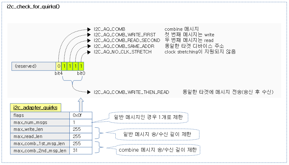
다음 그림은 quirks 체크를 수행하는 모습을 보여준다.
i2c_adapter_quirks 구조체
/**
 * struct i2c_adapter_quirks - describe flaws of an i2c adapter
 * @flags: see I2C_AQ_* for possible flags and read below
 * @max_num_msgs: maximum number of messages per transfer
 * @max_write_len: maximum length of a write message
 * @max_read_len: maximum length of a read message
 * @max_comb_1st_msg_len: maximum length of the first msg in a combined message
 * @max_comb_2nd_msg_len: maximum length of the second msg in a combined message
 *
 * Note about combined messages: Some I2C controllers can only send one message
 * per transfer, plus something called combined message or write-then-read.
 * This is (usually) a small write message followed by a read message and
 * barely enough to access register based devices like EEPROMs. There is a flag
 * to support this mode. It implies max_num_msg = 2 and does the length checks
 * with max_comb_*_len because combined message mode usually has its own
 * limitations. Because of HW implementations, some controllers can actually do
 * write-then-anything or other variants. To support that, write-then-read has
 * been broken out into smaller bits like write-first and read-second which can
 * be combined as needed.
 */
struct i2c_adapter_quirks {
        u64 flags;
        int max_num_msgs;
        u16 max_write_len;
        u16 max_read_len;
        u16 max_comb_1st_msg_len;
        u16 max_comb_2nd_msg_len;
};
- flags
- I2C_AQ_COMB(1)
- 메시지의 전송을 2개로 제한하고, max_comb_1st_msg_len 및 max_comb_2nd_msg_len 길이 체크를 사용한다.
- I2C_AQ_COMB_WRITE_FIRST(2)
- 첫 번째 combined 메시지를 먼저 write 해야한다.
- I2C_AQ_COMB_READ_SECOND(4)
- 두 번째 combined 메시지를 read 해야 한다.
- I2C_AQ_COMB_SAME_ADDR(8)
- 두 개의 메시지의 타겟 주소가 반드시 동일해야 한다.
- I2C_AQ_COMB_WRITE_THEN_READ(15)
- 같은 디바이스에 주소로 한 번 쓴 후, 다시 한 번 읽는다.
- 위의 4개 플래그를 동시에 사용하여 편리하게 사용할 수 있도록 하였다.
- I2C_AQ_NO_CLK_STRETCH(16)
- clock stretching을 지원하지 않는다.
- I2C_AQ_COMB(1)
- max_num_msgs
- 전송할 메시지의 최대 수
- max_write_len
- 최대 전송 길이
- max_read_len
- 최대 수신 길이
- max_comb_1st_msg_len
- 첫 번째 메시지 최대 길이
- max_comb_2nd_msg_len
- 두 번째 메시지 최대 길이
I2C Bus Recovery
I2C 버스 리커버리는 kernel v3.10-rc1에서 소개되었다.
Bus Clear
i2c 프로토콜 규격의 섹션 3.1.16에서 “Bus clear”라는 항목이 구현되었다.
- 드물게 클록(SCL) 또는 데이터 라인(SDA)가 고정되어 움직이지 않는 경우가 있다. 이러한 경우 다음과 같이 처리한다.
- A) 클록 (SCL)이 LOW로 고정된 경우
- I2C 디바이스에 HW 리셋 신호를 사용하여 버스를 리셋한다.
- 만일 I2C 디바이스에 HW 리셋 입력이 없으면 디바이스 전원을 껏다 켠다.
- B) 데이터 라인 (SDA)이 LOW로 고정된 경우
- 버스 마스터는 9 개의 클럭 펄스를 전송해야 한다.
- 버스를 LOW로 유지 한 장치는 9 클럭 내에서 이에 반응하여 해제해야 한다.
- 여전히 동작하지 않는 경우 A)와 같이 처리한다.
- A) 클록 (SCL)이 LOW로 고정된 경우
i2c 프로토콜 규격 – 섹션 3.1.16에서 “Bus clear” 원문
3.1.16 Bus clear

In the unlikely event where the clock (SCL) is stuck LOW, the preferential procedure is to reset the bus using the HW reset signal if your I2C devices have HW reset inputs. If the I2C devices do not have HW reset inputs, cycle power to the devices to activate the mandatory internal Power-On Reset (POR) circuit.

If the data line (SDA) is stuck LOW, the master should send nine clock pulses. The device that held the bus LOW should release it sometime within those nine clocks. If not, then
use the HW reset or cycle power to clear the bus.
i2c Bus Recovery 준비
i2c 버스를 리커버리하는 방법은 다음과 같은 방법들이 있다.
- 커널에 미리 준비된 i2c_generic_scl_recovery() 함수 사용
- 커널에 미리 준비된 i2c_generic_gpio_recovery() 함수 사용
- custom 리커버리 함수를 사용하여 직접 HW 설정
i2c_init_recovery()
drivers/i2c/base/i2c-core-base.c
static void i2c_init_recovery(struct i2c_adapter *adap)
{
        struct i2c_bus_recovery_info *bri = adap->bus_recovery_info;
        char *err_str;

        if (!bri)
                return;

        if (!bri->recover_bus) {
                err_str = "no recover_bus() found";
                goto err;
        }

        /* Generic GPIO recovery */
        if (bri->recover_bus == i2c_generic_gpio_recovery) {
                if (!gpio_is_valid(bri->scl_gpio)) {
                        err_str = "invalid SCL gpio";
                        goto err;
                }

                if (gpio_is_valid(bri->sda_gpio))
                        bri->get_sda = get_sda_gpio_value;
                else
                        bri->get_sda = NULL;

                bri->get_scl = get_scl_gpio_value;
                bri->set_scl = set_scl_gpio_value;
        } else if (bri->recover_bus == i2c_generic_scl_recovery) {
                /* Generic SCL recovery */
                if (!bri->set_scl || !bri->get_scl) {
                        err_str = "no {get|set}_scl() found";
                        goto err;
                }
        }

        return;
 err:
        dev_err(&adap->dev, "Not using recovery: %s\n", err_str);
        adap->bus_recovery_info = NULL;
}
i2c 버스 리커버리를 준비한다.
- 코드 라인 9~12에서 리커버리용 후크가 설정되지 않은 경우 함수를 빠져나간다.
- 코드 라인 15~27에서 gpio를 사용한 리커버리인 경우 scl_gpio 및 sda_gpio 핀 번호 값이 이상 없는지 확인한다. 그런 후 get_scl, set_scl 및 get_sda의 디폴트 함수를 설정 한다.
- 코드 라인 28~34에서 scl을 사용한 리커버리인 경우 set_scl 및 get_scl 후크가 지정되지 않은 경우 에러를 출력하고 함수를 빠져나간다.
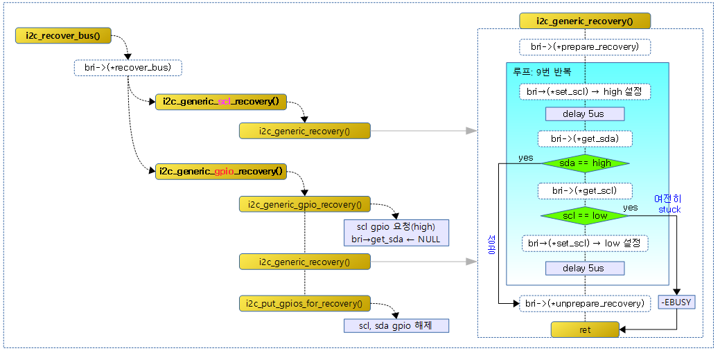
다음 그림은 i2c_init_recovery() 함수에서 3가지 타입의 (*recover_bus) 후크에 대해 처리하는 과정을 보여준다.
- A) SCL 리커버리: (*get_scl) 및 (*set_scl) 후크 함수 체크
- B) gpio 리커버리: (*get_scl), (*set_scl) 및 (*get_sda) 후크에 디폴트 함수 지정 및 scl_gpio, sda_gpio 핀 번호 체크
i2c_bus_recovery_info 구조체
include/linux/i2c.h
/**
 * struct i2c_bus_recovery_info - I2C bus recovery information
 * @recover_bus: Recover routine. Either pass driver's recover_bus() routine, or
 *      i2c_generic_scl_recovery() or i2c_generic_gpio_recovery().
 * @get_scl: This gets current value of SCL line. Mandatory for generic SCL
 *      recovery. Used internally for generic GPIO recovery.
 * @set_scl: This sets/clears SCL line. Mandatory for generic SCL recovery. Used
 *      internally for generic GPIO recovery.
 * @get_sda: This gets current value of SDA line. Optional for generic SCL
 *      recovery. Used internally, if sda_gpio is a valid GPIO, for generic GPIO
 *      recovery.
 * @prepare_recovery: This will be called before starting recovery. Platform may
 *      configure padmux here for SDA/SCL line or something else they want.
 * @unprepare_recovery: This will be called after completing recovery. Platform
 *      may configure padmux here for SDA/SCL line or something else they want.
 * @scl_gpio: gpio number of the SCL line. Only required for GPIO recovery.
 * @sda_gpio: gpio number of the SDA line. Only required for GPIO recovery.
 */
struct i2c_bus_recovery_info {
        int (*recover_bus)(struct i2c_adapter *);

        int (*get_scl)(struct i2c_adapter *);
        void (*set_scl)(struct i2c_adapter *, int val);
        int (*get_sda)(struct i2c_adapter *);

        void (*prepare_recovery)(struct i2c_adapter *);
        void (*unprepare_recovery)(struct i2c_adapter *);

        /* gpio recovery */
        int scl_gpio;
        int sda_gpio;
};
- (*recover_bus)
- 이 후크 함수를 호출하여 i2c 리커버리를 시도한다.
- scl 또는 sda가 low 상태에서 벗어나지 못하면 이 함수를 호출하여 9번의 클럭을 만들면서 sda가 high 상태로 풀려나는지 체크한다.
- 이 후크 함수를 호출하여 i2c 리커버리를 시도한다.
- (*get_scl)
- 시리얼 클럭(scl) 상태를 알아온다. 1/0
- (*set_scl)
- 시리얼 클럭(scl) 상태를 설정한다. 1/0
- (*get_sda)
- 시리얼 데이터(sda) 상태를 알아온다. 1/0
- (*prepare_recovery)
- 버스 리커버리를 수행하기 전에 먼저 처리할 일을 지정한다.
- (*prepare_recovery)
- 버스 리커버리를 완료한 후 처리할 일을 지정한다.
- scl_gpio
- gpio를 사용하여 시리얼 클럭(scl)을 만들 gpio 핀 번호
- sda_gpio
- gpio를 사용하여 시리얼 데이터(sda) 값을 읽을 핀 번호
i2c Bus Recovery 동작
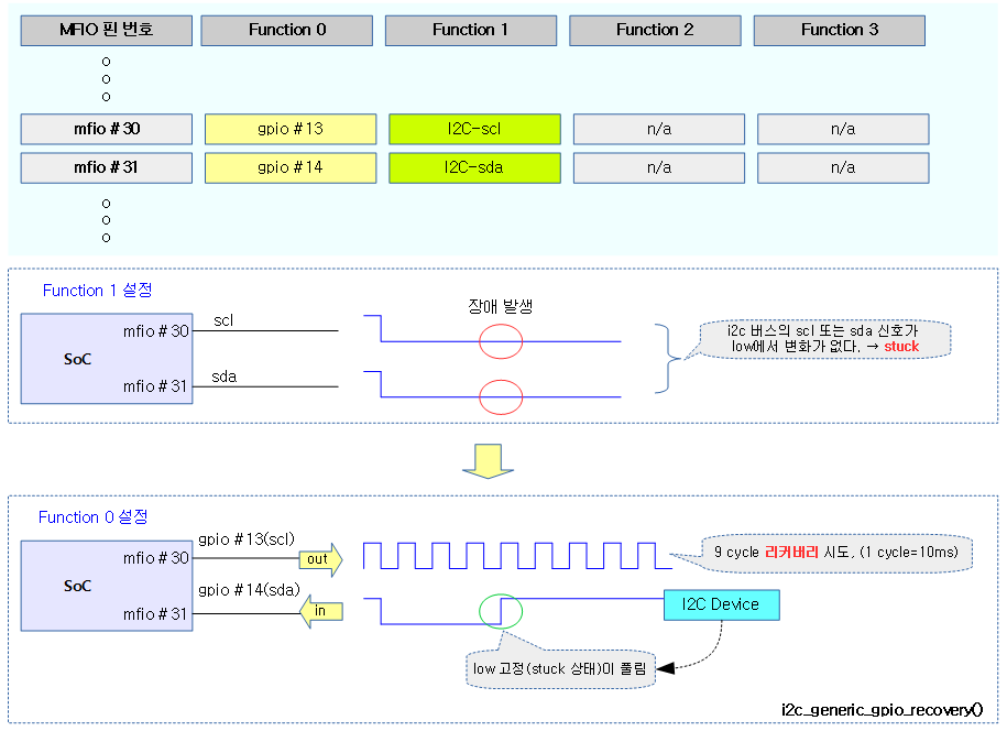
다음 그림은 i2c 버스가 stuck 상태일 때 100Khz의 클럭 펄스를 9번 만들어 i2c 버스가 리커버리를 시도하는 모습을 보여준다.
- 100Khz 클럭을 만들기 위해 매 사이클마다 low에서 5ms, high에서 5ms씩 delay해야 한다.
i2c_recover_bus()
drivers/i2c/base/i2c-core-base.c
int i2c_recover_bus(struct i2c_adapter *adap)
{
        if (!adap->bus_recovery_info)
                return -EOPNOTSUPP;

        dev_dbg(&adap->dev, "Trying i2c bus recovery\n");
        return adap->bus_recovery_info->recover_bus(adap);
}
EXPORT_SYMBOL_GPL(i2c_recover_bus);
i2c 버스 리커버리를 시도한다.
i2c_generic_scl_recovery()
drivers/i2c/base/i2c-core-base.c
int i2c_generic_scl_recovery(struct i2c_adapter *adap)
{
        return i2c_generic_recovery(adap);
}
EXPORT_SYMBOL_GPL(i2c_generic_scl_recovery);
scl 핀에 9번의 클럭을 만들어 i2c 버스 리커버리를 시도한다.
i2c_generic_recovery()
drivers/i2c/base/i2c-core-base.c
/*
 * We are generating clock pulses. ndelay() determines durating of clk pulses.
 * We will generate clock with rate 100 KHz and so duration of both clock levels
 * is: delay in ns = (10^6 / 100) / 2
 */
#define RECOVERY_NDELAY         5000
#define RECOVERY_CLK_CNT        9

static int i2c_generic_recovery(struct i2c_adapter *adap)
{
        struct i2c_bus_recovery_info *bri = adap->bus_recovery_info;
        int i = 0, val = 1, ret = 0;

        if (bri->prepare_recovery)
                bri->prepare_recovery(adap);

        bri->set_scl(adap, val);
        ndelay(RECOVERY_NDELAY);

        /*
         * By this time SCL is high, as we need to give 9 falling-rising edges
         */
        while (i++ < RECOVERY_CLK_CNT * 2) {
                if (val) {
                        /* Break if SDA is high */
                        if (bri->get_sda && bri->get_sda(adap))
                                        break;
                        /* SCL shouldn't be low here */
                        if (!bri->get_scl(adap)) {
                                dev_err(&adap->dev,
                                        "SCL is stuck low, exit recovery\n");
                                ret = -EBUSY;
                                break;
                        }
                }

                val = !val;
                bri->set_scl(adap, val);
                ndelay(RECOVERY_NDELAY);
        }

        if (bri->unprepare_recovery)
                bri->unprepare_recovery(adap);

        return ret;
}
scl 핀에 9번의 클럭을 만들어 i2c 버스 리커버리를 시도한다.
- 코드 라인 14~15에서 버스 리커버리를 시도하기 전에 먼저 수행해야 할 일을 처리한다.
- 코드 라인 17~41에서 9번 루프를 돌며 scl을 high 상태로 설정하고, sda 상태를 읽어본다. sda 상태가 high가 되면 리커버리가 되었으므로 루프를 벗어나다. 그렇지 않은 경우 scl 상태가 변경이 잘 되었는지 확인해본다. high 상태가 아니면 scl이 고정되어 stuck이 걸렸으므로 -EBUSY 에러를 반환한다. SCL 상태가 잘 변경이 되는 경우에는 계속하여 scl을 low 및 high로 변경해가면서 루프를 돌며 리커버리를 시도한다.
- 코드 라인 43~44에서 버스 리커버리를 완료한 후 수행해야 할 일을 처리한다.
i2c_generic_gpio_recovery()
drivers/i2c/base/i2c-core-base.c
int i2c_generic_gpio_recovery(struct i2c_adapter *adap)
{
        int ret;

        ret = i2c_get_gpios_for_recovery(adap);
        if (ret)
                return ret;

        ret = i2c_generic_recovery(adap);
        i2c_put_gpios_for_recovery(adap);

        return ret;
}
EXPORT_SYMBOL_GPL(i2c_generic_gpio_recovery);
gpio 모드로 변경하여 scl을 준비하고 9번의 클럭을 만들어 i2c 버스 리커버리를 시도한다. 처리한 후 다시 gpio 모드를 해제한다.
- pinmux에 i2c 기능과 gpio 기능이 모두 있는 경우 i2c 기능으로 동작하다가 리커버리가 필요할 때 gpio 모드로 전환하여 리커버리를 수행할 수 있다.
다음 그림은 pinmux를 통해 i2c 펑션 모드로 사용하다가 i2c 버스 리커버리를 시도하는 모습을 보여준다.
- gpio 펑션 모드로 전환 시켜 i2c 버스 리커버리를 하는 것을 알 수 있다.
i2c_get_gpios_for_recovery()
drivers/i2c/base/i2c-core-base.c
static int i2c_get_gpios_for_recovery(struct i2c_adapter *adap)
{
        struct i2c_bus_recovery_info *bri = adap->bus_recovery_info;
        struct device *dev = &adap->dev;
        int ret = 0;

        ret = gpio_request_one(bri->scl_gpio, GPIOF_OPEN_DRAIN |
                        GPIOF_OUT_INIT_HIGH, "i2c-scl");
        if (ret) {
                dev_warn(dev, "Can't get SCL gpio: %d\n", bri->scl_gpio);
                return ret;
        }

        if (bri->get_sda) {
                if (gpio_request_one(bri->sda_gpio, GPIOF_IN, "i2c-sda")) {
                        /* work without SDA polling */
                        dev_warn(dev, "Can't get SDA gpio: %d. Not using SDA polling\n",
                                        bri->sda_gpio);
                        bri->get_sda = NULL;
                }
        }

        return ret;
}
scl_gpio 번 핀을 scl로 사용하기 위해 open-drain 설정으로 초기 high 출력 상태로 요청한다. (*get_sda) 후크가 사용되는 경우 sda_gpio 번 핀을 sda로 input mode로 사용 요청한다.
i2c_put_gpios_for_recovery()
drivers/i2c/base/i2c-core-base.c
static void i2c_put_gpios_for_recovery(struct i2c_adapter *adap)
{
        struct i2c_bus_recovery_info *bri = adap->bus_recovery_info;

        if (bri->get_sda)
                gpio_free(bri->sda_gpio);

        gpio_free(bri->scl_gpio);
}
리커버리를 종료하였으므로 scl_gpio 및 sda_gpio 번 핀을 gpio 모드에서 해제한다.
gpio 리커버리에서 사용하는 세 함수들
get_scl_gpio_value()
drivers/i2c/base/i2c-core-base.c
static int get_scl_gpio_value(struct i2c_adapter *adap)
{
        return gpio_get_value(adap->bus_recovery_info->scl_gpio);
}
scl_gpio 번 핀의 값을 알아온다.
set_scl_gpio_value()
drivers/i2c/base/i2c-core-base.c
static void set_scl_gpio_value(struct i2c_adapter *adap, int val)
{
        gpio_set_value(adap->bus_recovery_info->scl_gpio, val);
}
scl_gpio 번 핀에 값을 출력한다.
get_sda_gpio_value()
drivers/i2c/base/i2c-core-base.c
static int get_sda_gpio_value(struct i2c_adapter *adap)
{
        return gpio_get_value(adap->bus_recovery_info->sda_gpio);
}
sda_gpio 번 핀의 값을 알아온다.
I2C 전송 및 버스 락
I2C 버스 락
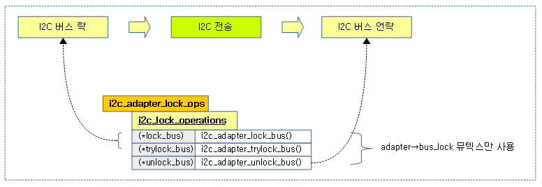
i2c 호스트 컨트롤러를 통해 i2c 버스에 데이터를 송/수신할 때 먼저 버스를 점유하기 위해 i2c 버스 락을 걸고 사용한다. 이 때 대부분의 호스트 컨트롤러의 adapter 인터페이스는 lock_ops가 주어지지 않았을 때 디폴트로 adapter의 bus_lock 뮤텍스를 사용한다.
다음 그림은 i2c 전송 전에 디폴트 i2c 버스 락 오퍼레이션인 adapter의 bus_lock 뮤텍스를 사용하는 것을 보여준다.
- i2c-mux 호스트 컨트롤러를 사용할 때 채널별로 있는 adapter 들의 lock 오퍼레이션은 별도로 지정하여 사용한다.
i2c_adapter_lock_bus()
drivers/i2c/i2c-core-base.c
/**
 * i2c_adapter_lock_bus - Get exclusive access to an I2C bus segment
 * @adapter: Target I2C bus segment
 * @flags: I2C_LOCK_ROOT_ADAPTER locks the root i2c adapter, I2C_LOCK_SEGMENT
 *      locks only this branch in the adapter tree
 */
static void i2c_adapter_lock_bus(struct i2c_adapter *adapter,
                                 unsigned int flags)
{
        rt_mutex_lock(&adapter->bus_lock);
}
adapter에 있는 버스 뮤텍스 락을 건다.
i2c_adapter_trylock_bus()
drivers/i2c/i2c-core-base.c
/**
 * i2c_adapter_trylock_bus - Try to get exclusive access to an I2C bus segment
 * @adapter: Target I2C bus segment
 * @flags: I2C_LOCK_ROOT_ADAPTER trylocks the root i2c adapter, I2C_LOCK_SEGMENT
 *      trylocks only this branch in the adapter tree
 */
static int i2c_adapter_trylock_bus(struct i2c_adapter *adapter,
                                   unsigned int flags)
{
        return rt_mutex_trylock(&adapter->bus_lock);
}
adapter에 있는 버스 뮤텍스 락을 시도한다.
i2c_adapter_unlock_bus()
drivers/i2c/i2c-core-base.c
/**
 * i2c_adapter_unlock_bus - Release exclusive access to an I2C bus segment
 * @adapter: Target I2C bus segment
 * @flags: I2C_LOCK_ROOT_ADAPTER unlocks the root i2c adapter, I2C_LOCK_SEGMENT
 *      unlocks only this branch in the adapter tree
 */
static void i2c_adapter_unlock_bus(struct i2c_adapter *adapter,
                                   unsigned int flags)
{
        rt_mutex_unlock(&adapter->bus_lock);
}
adapter에 있는 버스 뮤텍스 락을 해제한다.
I2C 전송 Core
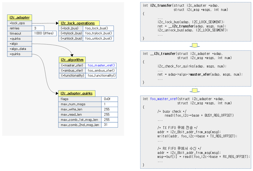
i2c 전송은 i2c_algorithm에 구현되어 있는 i2c용 전송 후크를 이용한다. 만일 smbus 전송이 필요한 경우 smbus용 후크도 지정하여 사용할 수 있다.
다음 그림은 i2c 전송에 관여하는 lock operation과 알고리즘 및 전송 제한 값 및 i2c 전송 함수의 호출 단계를 보여준다.
i2c_transfer()
drivers/i2c/i2c-core-base.c
/**
 * i2c_transfer - execute a single or combined I2C message
 * @adap: Handle to I2C bus
 * @msgs: One or more messages to execute before STOP is issued to
 *      terminate the operation; each message begins with a START.
 * @num: Number of messages to be executed.
 *
 * Returns negative errno, else the number of messages executed.
 *
 * Note that there is no requirement that each message be sent to
 * the same slave address, although that is the most common model.
 */
int i2c_transfer(struct i2c_adapter *adap, struct i2c_msg *msgs, int num)
{
        int ret;

        /* REVISIT the fault reporting model here is weak:
         *
         *  - When we get an error after receiving N bytes from a slave,
         *    there is no way to report "N".
         *
         *  - When we get a NAK after transmitting N bytes to a slave,
         *    there is no way to report "N" ... or to let the master
         *    continue executing the rest of this combined message, if
         *    that's the appropriate response.
         *
         *  - When for example "num" is two and we successfully complete
         *    the first message but get an error part way through the
         *    second, it's unclear whether that should be reported as
         *    one (discarding status on the second message) or errno
         *    (discarding status on the first one).
         */

        if (adap->algo->master_xfer) {
#ifdef DEBUG
                for (ret = 0; ret < num; ret++) {
                        dev_dbg(&adap->dev,
                                "master_xfer[%d] %c, addr=0x%02x, len=%d%s\n",
                                ret, (msgs[ret].flags & I2C_M_RD) ? 'R' : 'W',
                                msgs[ret].addr, msgs[ret].len,
                                (msgs[ret].flags & I2C_M_RECV_LEN) ? "+" : "");
                }
#endif

                if (in_atomic() || irqs_disabled()) {
                        ret = i2c_trylock_bus(adap, I2C_LOCK_SEGMENT);
                        if (!ret)
                                /* I2C activity is ongoing. */
                                return -EAGAIN;
                } else {
                        i2c_lock_bus(adap, I2C_LOCK_SEGMENT);
                }

                ret = __i2c_transfer(adap, msgs, num);
                i2c_unlock_bus(adap, I2C_LOCK_SEGMENT);

                return ret;
        } else {
                dev_dbg(&adap->dev, "I2C level transfers not supported\n");
                return -EOPNOTSUPP;
        }
}
EXPORT_SYMBOL(i2c_transfer);
i2c 버스에 락을 건채 요청한 메시지 수 만큼 전송을 수행한다. 성공 시 0을 반환한다.
- 코드 라인 22에서 i2c 전송을 지원하는 후크 함수가 있는 경우이다.
- pc의 smbus는 i2c 전송은 지원하지 않고, smbus 전송만 지원하는 경우가 있다.
- 코드 라인 34~38에서 전송을 하기 전에 먼저 버스를 점유해야 한다. irq context이거나 preempt disable 상태인 경우 i2c bus 락을 시도한다. 이 때 실패하는 경우 -EAGAIN 에러를 반환한다.
- 코드 라인 39~41에서 i2c 버스 락을 건다.
- 코드 라인 43~44에서 요청한 메시지 수 만큼 전송을 한 후 i2c 버스 언락을 한다.
__i2c_transfer()
drivers/i2c/i2c-core-base.c
/**
 * __i2c_transfer - unlocked flavor of i2c_transfer
 * @adap: Handle to I2C bus
 * @msgs: One or more messages to execute before STOP is issued to
 *      terminate the operation; each message begins with a START.
 * @num: Number of messages to be executed.
 *
 * Returns negative errno, else the number of messages executed.
 *
 * Adapter lock must be held when calling this function. No debug logging
 * takes place. adap->algo->master_xfer existence isn't checked.
 */
int __i2c_transfer(struct i2c_adapter *adap, struct i2c_msg *msgs, int num)
{
        unsigned long orig_jiffies;
        int ret, try;

        if (adap->quirks && i2c_check_for_quirks(adap, msgs, num))
                return -EOPNOTSUPP;

        /* i2c_trace_msg gets enabled when tracepoint i2c_transfer gets
         * enabled.  This is an efficient way of keeping the for-loop from
         * being executed when not needed.
         */
        if (static_key_false(&i2c_trace_msg)) {
                int i;
                for (i = 0; i < num; i++)
                        if (msgs[i].flags & I2C_M_RD)
                                trace_i2c_read(adap, &msgs[i], i);
                        else
                                trace_i2c_write(adap, &msgs[i], i);
        }

        /* Retry automatically on arbitration loss */
        orig_jiffies = jiffies;
        for (ret = 0, try = 0; try <= adap->retries; try++) {
                ret = adap->algo->master_xfer(adap, msgs, num);
                if (ret != -EAGAIN)
                        break;
                if (time_after(jiffies, orig_jiffies + adap->timeout))
                        break;
        }

        if (static_key_false(&i2c_trace_msg)) {
                int i;
                for (i = 0; i < ret; i++)
                        if (msgs[i].flags & I2C_M_RD)
                                trace_i2c_reply(adap, &msgs[i], i);
                trace_i2c_result(adap, i, ret);
        }

        return ret;
}
EXPORT_SYMBOL(__i2c_transfer);
i2c 버스에 요청한 메시지 수 만큼 전송을 수행한다. 성공 시 0을 반환한다.
- 코드 라인 6~7에서 quirks 전송 제한에 걸린 경우 -EOPNOTSUPP 에러를 반환한다.
- 코드 라인 13~20에서 읽고 쓸 메시지에 대해 trace 출력을 한다.
- 코드 라인 23~30에서 i2c 전송을 한다. 전송 후 -EAGAIN 에러인 경우 retries 수 이내에서 루프를 돌며 시도한다. 만일 제한 시간을 초과하는 경우 재시도를 하지 않는다.
- 코드 라인 32~38에서 읽은 메시지가 있는 경우 이에 대한 trace 출력을 한다.
i2c 전송 (for bcm-i2c-iproc)
broadcom ns2에 내장된 i2c에 사용하는 bcm-i2c-iproc 드라이버에서 사용하는 전송함수을 예로 알아본다.
bcm_iproc_i2c_xfer()
drivers/i2c/busses/i2c-bcm-iproc.c
static int bcm_iproc_i2c_xfer(struct i2c_adapter *adapter,
                              struct i2c_msg msgs[], int num)
{
        struct bcm_iproc_i2c_dev *iproc_i2c = i2c_get_adapdata(adapter);
        int ret, i;

        /* go through all messages */
        for (i = 0; i < num; i++) {
                ret = bcm_iproc_i2c_xfer_single_msg(iproc_i2c, &msgs[i]);
                if (ret) {
                        dev_dbg(iproc_i2c->device, "xfer failed\n");
                        return ret;
                }
        }

        return num;
}
요청한 메시지 수 만큼 메시지들을 전송한다. 성공 시 메시지 수가 반환된다. 실패의 경우 음수를 반환한다.
bcm_iproc_i2c_xfer_single_msg()
drivers/i2c/busses/i2c-bcm-iproc.c -1/2-
static int bcm_iproc_i2c_xfer_single_msg(struct bcm_iproc_i2c_dev *iproc_i2c,
                                         struct i2c_msg *msg)
{
        int ret, i;
        u8 addr;
        u32 val;
        unsigned int tx_bytes;
        unsigned long time_left = msecs_to_jiffies(I2C_TIMEOUT_MSEC);

        /* check if bus is busy */
        if (!!(readl(iproc_i2c->base + M_CMD_OFFSET) &
               BIT(M_CMD_START_BUSY_SHIFT))) {
                dev_warn(iproc_i2c->device, "bus is busy\n");
                return -EBUSY;
        }

        iproc_i2c->msg = msg;

        /* format and load slave address into the TX FIFO */
        addr = i2c_8bit_addr_from_msg(msg);
        writel(addr, iproc_i2c->base + M_TX_OFFSET);

        /*
         * For a write transaction, load data into the TX FIFO. Only allow
         * loading up to TX FIFO size - 1 bytes of data since the first byte
         * has been used up by the slave address
         */
        tx_bytes = min_t(unsigned int, msg->len, M_TX_RX_FIFO_SIZE - 1);
        if (!(msg->flags & I2C_M_RD)) {
                for (i = 0; i < tx_bytes; i++) {
                        val = msg->buf[i];

                        /* mark the last byte */
                        if (i == msg->len - 1)
                                val |= 1 << M_TX_WR_STATUS_SHIFT;

                        writel(val, iproc_i2c->base + M_TX_OFFSET);
                }
                iproc_i2c->tx_bytes = tx_bytes;
        }

        /* mark as incomplete before starting the transaction */
        reinit_completion(&iproc_i2c->done);
        iproc_i2c->xfer_is_done = 0;

        /*
         * Enable the "start busy" interrupt, which will be triggered after the
         * transaction is done, i.e., the internal start_busy bit, transitions
         * from 1 to 0.
         */
        val = BIT(IE_M_START_BUSY_SHIFT);

        /*
         * If TX data size is larger than the TX FIFO, need to enable TX
         * underrun interrupt, which will be triggerred when the TX FIFO is
         * empty. When that happens we can then pump more data into the FIFO
         */
        if (!(msg->flags & I2C_M_RD) &&
            msg->len > iproc_i2c->tx_bytes)
                val |= BIT(IE_M_TX_UNDERRUN_SHIFT);

        writel(val, iproc_i2c->base + IE_OFFSET);
1개의 메시지를 전송한다. 실패 시 음수를 반환한다.
- 코드 라인 11~15에서 이미 명령이 시작되어 처리되고 있는 중이라 i2c 버스 Busy 상태이다. 이러한 경우 -EBUSY 에러를 반환한다.
- 코드 라인 17~21에서 메시지에서 7비트 주소와 R/W 비트를 추가한 8비트 값을 tx 레지스터에 기록한다.
- 코드 라인 28에서 전송할 메시지 길이를 최대 63바이트 범위이내로 제한한다.
- 코드 라인 28~40에서 Read 메시지가 아니면 송신할 바이트 수 만큼 순회하며 tx 레지스터에 기록한다. 32비트 tx 레지스터에 1 바이트를 기록할 때 tx 레지스터의 msb를 항상 1로 설정한다.
- 예) { 0x30, 0x40, 0x50, 0x60 } 을 tx 레지스터에 기록 시
- -> { 0x8000_0030, 0x8000_0040, 0x8000_0050, 0x8000_0060 }
- 예) { 0x30, 0x40, 0x50, 0x60 } 을 tx 레지스터에 기록 시
- 코드 라인 43~44에서 전송이 완료되었음을 알린다.
- 코드 라인 50~61에서 IE 레지스터에 값을 기록한다.
- start_busy 비트와 송신 메시지인 경우 adapter의 tx FIFO 버퍼 크기보다 큰 경우 tx underrun 비트를 합친 값이다.
drivers/i2c/busses/i2c-bcm-iproc.c -2/2-
        /*
         * Now we can activate the transfer. For a read operation, specify the
         * number of bytes to read
         */
        val = BIT(M_CMD_START_BUSY_SHIFT);
        if (msg->flags & I2C_M_RD) {
                val |= (M_CMD_PROTOCOL_BLK_RD << M_CMD_PROTOCOL_SHIFT) |
                       (msg->len << M_CMD_RD_CNT_SHIFT);
        } else {
                val |= (M_CMD_PROTOCOL_BLK_WR << M_CMD_PROTOCOL_SHIFT);
        }
        writel(val, iproc_i2c->base + M_CMD_OFFSET);

        time_left = wait_for_completion_timeout(&iproc_i2c->done, time_left);

        /* disable all interrupts */
        writel(0, iproc_i2c->base + IE_OFFSET);
        /* read it back to flush the write */
        readl(iproc_i2c->base + IE_OFFSET);

        /* make sure the interrupt handler isn't running */
        synchronize_irq(iproc_i2c->irq);

        if (!time_left && !iproc_i2c->xfer_is_done) {
                dev_err(iproc_i2c->device, "transaction timed out\n");

                /* flush FIFOs */
                val = (1 << M_FIFO_RX_FLUSH_SHIFT) |
                      (1 << M_FIFO_TX_FLUSH_SHIFT);
                writel(val, iproc_i2c->base + M_FIFO_CTRL_OFFSET);
                return -ETIMEDOUT;
        }

        ret = bcm_iproc_i2c_check_status(iproc_i2c, msg);
        if (ret) {
                /* flush both TX/RX FIFOs */
                val = (1 << M_FIFO_RX_FLUSH_SHIFT) |
                      (1 << M_FIFO_TX_FLUSH_SHIFT);
                writel(val, iproc_i2c->base + M_FIFO_CTRL_OFFSET);
                return ret;
        }

        /*
         * For a read operation, we now need to load the data from FIFO
         * into the memory buffer
         */
        if (msg->flags & I2C_M_RD) {
                for (i = 0; i < msg->len; i++) {
                        msg->buf[i] = (readl(iproc_i2c->base + M_RX_OFFSET) >>
                                      M_RX_DATA_SHIFT) & M_RX_DATA_MASK;
                }
        }

        return 0;
}
- 코드 라인 5~12에서 M_CMD 레지스터에 적절한 값을 기록한다.
- 코드 라인 14에서 남은 타임아웃 시간만큼 전송이 완료될 때 까지 기다린다.
- 코드 라인 17~19에서 모든 인터럽트를 disable하고 write 플러쉬를 수행한다.
- 코드 라인 22에서 인터럽트 핸들러가 처리 중인 경우 완료될 때 까지 대기한다.
- 코드 라인 24~32에서 시간이 만료되었고 여전히 전송이 완료되지 않은 경우 RX, TX FIFO 버퍼를 flush한 후 -ETIMEOUT 에러를 반환한다.
- 코드 라인 34~41에서 다시 i2c 버스 상태가 성공(0) 상태가 아닌 경우에도 RX, TX FIFO 버퍼를 flush한 후 에러를 반환한다.
- 코드 라인 47~52에서 read 메시지 요청인 경우 M_RX 레지스터에서 요청한 메시지 길이 만큼 반복하여 읽어온다.
- 수신한 데이터의 하위 8비트만 mask하여 바이트로 저장한다.
Broadcom ns2 I2C Register
다음 그림은 broadcom ns2 SoC 내부에 임베드된 i2c 호스 컨트롤러에서 사용되는 주요 레지스터들이다.
참고
- I2C Subsystem -1- (Basic) | 문c
- I2C Subsystem -2- (Core) | 문c
- I2C Subsystem -3- (Transfer) | 문c – 현재글
- i2C Subsystem -4- (I2C-Mux) | 문c
- Documentation/i2c/ – kernel.org
- Documentation/i2c/dev-interface.txt – kernel.org
- I2C | sparkfun
- I2C – What’s That? | i2c-bus.org
- What is I2C (inter-‐IC) | Piazza – 다운로드 pdf
- I2C manual – NXP Semiconductors | NXP – 다운로드 pdf
- I2C-bus specification and user manual Rev. 6 — 4 April 2014 | NXP – 다운로드 pdf
- PCA954X FAMILY OF I²C / SMBus MULTIPLEXERS and SWITCHES | Philips – 다운로드 pdf


안녕 하세요. 정말 많은 참고를 하고 있습니다. 감사 드립니다.
설명하는 내공이 정말 엄청나시네요 ㄷㄷ..
기존에 Arm 을 사용하다가 Intel 계열로 변경해야 하는데..Chip Vendor 에서 제공해 주는 SDK 를 사용하다가
바닥부터 다시 하려니 쉽지가 않네요..ㅜ
혹시 I2C clock speed 를 변경할 수 있는 API 나 소스를 알 수 있을까요?
device tree 가 아닌 ACPI 를 사용하는터라.그쪽에 대한 사항을 알고 계시면 염치 불구하고 여쭙겠습니다.
안녕하세요?
저도 ACPI 스크립트들은 인터넷 검색으로만 봤습니다.
인텔 칩 계열에서 I2C를 사용하는 것이 흔한 일이 아니죠?
i2c 클럭 스피드는 i2c_acpi_find_bus_speed() API 함수를 통해 ACPI 정보를 취득하여 변경하는 것으로 되어 있습니다.
제 경험도 모자라 큰 도움이 안되는 군요.
수고하세요.