QEMU 에뮬레이션(arm64)

PC 환경에서 arm64 커널을 에뮬레이션해보자.


목적

사용자 OS로 64bit x86 PC Window 환경에서 virtualbox를 사용하여 호스트 OS용도로 우분투 리눅스를 사용하고 있는데, 이 우분투에서 QEMU를 사용하여 게스트 OS로 arm64 커널을 사용하게 한다.

  • 게스트 OS로 arm 연합인 Linaro에서 안정적으로 제공하는 커널인 LSK(Linaro Stable Kernel) 커널을 사용한다. 그리고 Linaro Releases 사이트에서 같이 제공하는 여러 가지 형태의 루트파일시스템을 사용한다.
  • 게스트 OS에서 인터넷이 동작해야 한다.
  • 게스트 OS에서 gcc 컴파일 환경이 있어야 한다.


테스트 환경 조건

  • 사용자 OS
    • x86 아키텍처(intel 64bit)를 사용하는 PC
    • Window 8 또는 10 (반드시 64비트 운영체제여야 함)
    • 호스트 OS로 리눅스를 사용하기 위해 VirutalBox 5.1 사용
  • 호스트 OS
    • Ubuntu 64bit 14.04 이상 (반드시 64비트 운영체제여야 함)
    • QEMU 2.9 이상
  • 게스트 OS (arm64)
    • LSK 4.4 이상
      • LSK 4.14 추천


사전 준비 작업

다음 항목들이 사전에 준비되어 있어야 한다. 이 항목들의 설치 방법은 설명하지 않는다.

  • 64bit Windows 10
  • VirtualBox 5.1
  • 64bit Ubuntu 14.4 이상
    • kernel 4.14 이상의 빌드환경을 위해서는 Ubuntu 64bit 18.04 권장
  • Linaro 툴체인 5.3 이상
    • Ubuntu 18.04의 경우 gcc 7.3 권장
  • gcc 컴파일러 4.8.4
    • Ubuntu 18.04의 경우 gcc 7.3 권장
  • QEMU 2.9 이상
    • Guest OS 실행 시 콘솔 출력이 안되는 경우 qemu 소스를 다운로드 및  빌드 후 설치 권장
    • Ubuntu 18.04의 경우 QEMU 2.11 권장
  • 기타 툴 (각자 호스트 OS 환경에 맞춰…)
    • gawk wget git-core diffstat unzip texinfo gcc-multilib build-essential chrpath socat libsdl1.2-dev xterm lib32stdc++6 lib32z1 libssl-dev device-tree-compiler vim autogen autoconf libtool flex bison ncurses-dev uuid-dev python-dev python-crypto libsdl2-dev libbsd libattr-devel screen qemu-utils cloud-utils bridge-utils dnsmasq uml-utilities


에뮬레이션 모드 vs VM 가속화 모드(KVM)

QEMU는 에뮬레이션 모드와 VM 가속화 모드가 있다는 것을 미리 알아두어야 혼동이되지 않는다.

  • 에뮬레이션 모드
    • 호스트 OS용 아키텍처와 게스트 OS용 아키텍처 코드를 실행할 수 있다.
    • 예: x86 pc 호스트 환경에서 aarch64 커널을 구동
  • 가속화 모드(KVM 모드)
    • “–kvm” 플래그를 사용하여 호스트와 게스트 os가 동일한 아키텍처인 경우 VM을 가속화할 수 있다.
    • 예: aarch64 호스트(임베디드 등) 환경에서 arm64 커널(aarch64) 구동


1. VirtualBox 주요 네트워크 설정


네트웍 환경

QEMU를 사용하면서 가장 어려운 설정이 네트워크 부분이다. 다음 그림과 같은 네트워크 환경으로 구성할 예정이다.

  • 여러 가지 제약 조건이 걸려있기 때문에 잘 이해하고 준비해두어야 한다.


VirtualBox 환경 설정

아래 그림과 같이 VirtualBox에 NAT 네트워크를 20.0.2.0/24 네트워크 대역으로 만든다.

  • VirtualBox의 default NAT 네트워크 대역은 10.0.2.x/24를 사용하는데 이를 변경하여 20.0.2.x/24 대역을 사용한다.
  • 인터넷 연결이 제한된 호스트 전용 네트워크는 구성하지 않는다.


VirtualBox에서 Ubuntu OS 네트워크 설정

64비트용 우분투 OS의 네트워크 설정을 다음과 같이 변경한다.


Ubuntu 부팅 후 네트워크 설정

호스트 OS인 우분투 버전에 따라 NIC 인터페이스 이름이 아래 둘 중 하나로 결정된다.
  • eth0
  • enp0s3 (우분투 15.10 이상부터 적용)
네트워크 설정을 관리하는 방법은 다음 두 가지가 있는데 여기에서는 /etc/network/interface를 사용한다.
  • /etc/network/interface (전통적 방법)
  • Network Manager


/etc/network/interfaces 파일 수정

호스트 OS의 브리지 설정 및 NAT forwading을 위해 /etc/network/interface 파일을 다음과 같이 수정한다.

  • 게스트 OS를 위한 promisc 설정
    • enp0s3(eth0) 인터페이스에 반드시 PROMISC가 설정되어 있어야 bridge 내에 추가되는 tap0 인터페이스에 enp0s3로 수신되는 모든 패킷을 tap 인터페이스도 브릿지되어 전달될 수 있도록 한다.
    • 만일 promisc가 enp0s3(eth0)에 설정되지 않은 경우 enp0s3가 수신한 패킷 중 dest MAC이 enp0s3의 MAC이 아닌 경우 filter 처리하므로 게스트 OS의 네트웍 드라이버에서 사용하는 MAC이 tap0를 통해 수신할 수 없다.
      • 게스트 OS가 자신의 패킷을 전송할 수는 있어도 자신에게 오는 인터넷 패킷을 수신할 수 없다.
  • 게스트 OS를 위한 NAT 설정
    • 아래 스크립트의 가장 마지막 두 줄에 해당한다.
$ sudo vi /etc/network/interfaces
auto lo
iface lo inet loopback

auto enp0s3
iface enp0s3 inet manual
    address 0.0.0.0
    netmask 255.255.255.0

auto virbr0
iface virbr0 inet static
        address 20.0.2.4
        netmask 255.255.255.0
        gateway 20.0.2.2
        bridge_ports enp0s3
        bridge_stp off

up /sbin/ifconfig enp0s3 promisc
up sysctl net.ipv4.ip_forward=1
up iptables -t nat -A POSTROUTING -o virbr0 -j MASQUERADE


Network Manager 동작 정지

네트워크 매니저가 동작하지 못하게  /etc/NetworkManager/NetworkManager.conf 파일을 다음과 같이 수정한다.

  • managed=false와 같이 수정한다.
$ sudo vi /etc/NetworkManager/NetworkManger.conf
[main]
plugins=ifupdown,keyfile,ofono
dns=dnsmasq

no-auto-default=08:00:27:15:4C:52,

[ifupdown]
managed=false


DNS Server 설정

최근에는 dns 설정을 위해 /etc/resolv.conf 파일의 직접적인 수정은 허용하지 않는다. 따라서 다음과 같은 동작을 수행한다.

  • 아래 예에서는 dns server로 168.126.63.1을 사용하였다. (적절히 사용자가 선호하는 dns server를 1개 이상 등록한다)
$ sudo vi /etc/resolvconf/resolv.conf.d/tail
nameserver 168.126.63.1

$ sudo service resolvconf restart


등록이 잘 되었는지 확인해본다.

$ cat /etc/resolv.conf
nameserver 127.0.0.1
nameserver 168.126.63.1


호스트 OS 네트웍 테스트

다음과 같이 우분트를 리부팅한 후 네트웍이 정상 동작하는지 확인한다.

$ sudo reboot

   (리부팅)

$ ifconfig
enp0s3    Link encap:Ethernet  HWaddr 08:00:27:59:bc:f3  
          UP BROADCAST RUNNING PROMISC MULTICAST  MTU:1500  Metric:1
          ...
virbr0    Link encap:Ethernet  HWaddr 08:00:27:59:bc:f3  
          inet addr:20.0.2.4  Bcast:20.0.2.255  Mask:255.255.255.0
          inet6 addr: fe80::a00:27ff:fe59:bcf3/64 Scope:Link
          UP BROADCAST RUNNING MULTICAST  MTU:1500  Metric:1
          ...
$ route
Kernel IP routing table
Destination     Gateway         Genmask         Flags Metric Ref    Use Iface
default         20.0.2.2        0.0.0.0         UG    0      0        0 virbr0
20.0.2.0        *               255.255.255.0   U     0      0        0 virbr0
link-local      *               255.255.0.0     U     1000   0        0 virbr0

$ ping hello.net
PING hello.net (52.216.83.66) 56(84) bytes of data.
64 bytes from 52.216.83.66: icmp_seq=1 ttl=37 time=186 ms
64 bytes from 52.216.83.66: icmp_seq=2 ttl=37 time=187 ms


탭(tap) 인터페이스 생성

게스트 OS가 호스트 OS와의 통신 뿐만 아니라 외부 인터넷망과 연동하려면 tap 인터페이스를 준비하여야 한다.


탭 인터페이스 생성 스크립트 준비

호스트 OS에 tap0 인터페이스를 만들고 브리지에 등록하는 스크립트를 준비한다.

  • 호스트 OS 버전에 따라 이더넷 인터페이스 명이 달라지므로 아래 ENET 변수를 사용하는 호스트 이더넷 인터페이스명에 맞게 수정한다.
    • enp0s3 (우분투 15.04 이상)
    • eth0
  • 호스트 OS 커널이 tap 인터페이스를 만들 수 있도록 tun 디바이스가 준비되어 있어야 한다.
    • 확인: 호스트 OS인 우분투에 /dev/net/tun 파일이 존재해야 한다.
  • 주의: tap0 인터페이스는 사용자 권한에서 접근이 가능해야 하므로 현재 사용자명을 사용하여 생성한다.
    • 아래 스크립트에서 sudo tunctl -u {WHOAMI} 부분을 참고한다.
$ mkdir qq2
$ cd qq2
$ vi tap.sh
WHOAMI=$(whoami)

echo add tap0 to virbr0 bridge
echo ------------------------------------------------------
sudo tunctl -d tap0
sudo tunctl -u ${WHOAMI}
sudo ifconfig tap0 0.0.0.0 up
sudo brctl addif virbr0 tap0

$ chmod 755 ./tap.sh


탭 인터페이스 생성 및 체크

tap.sh 스크립트를 동작시켜 tap 인터페이스를 생성한다.

$ ./tap.sh
add tap0 to virbr0 bridge
------------------------------------------------------
[sudo] password for jake:
Set 'tap0' nonpersistent
Set 'tap0' persistent and owned by uid 1000


네트워크 동작 확인

다음 명령들을 통해 tap 인터페이스 생성 후 브리지에 잘 포함되었는지와 네트웍이 정상 동작하는 것을 확인한다.

  • 사용하는 리눅스 패키지 및 버전에 따라 enp0s3 대신 eth0가 나올 수도 있다.
$ ifconfig
enp0s3    Link encap:Ethernet  HWaddr 08:00:27:59:bc:f3  
          UP BROADCAST RUNNING PROMISC MULTICAST  MTU:1500  Metric:1
          ...
tap0      Link encap:Ethernet  HWaddr 02:e4:fd:72:d5:13  
          UP BROADCAST MULTICAST  MTU:1500  Metric:1
          ...
virbr0    Link encap:Ethernet  HWaddr 02:e4:fd:72:d5:13  
          inet addr:20.0.2.4  Bcast:20.0.2.255  Mask:255.255.255.0
          ...
$ brctl show
bridge name    bridge id        STP enabled    interfaces
virbr0        8000.02e4fd72d513    no          enp0s3
                                               tap0

$ ping hello.net
PING hello.net (52.216.18.242) 56(84) bytes of data.
64 bytes from 52.216.18.242: icmp_seq=1 ttl=33 time=239 ms
64 bytes from 52.216.18.242: icmp_seq=2 ttl=33 time=235 ms

$ route
Kernel IP routing table
Destination     Gateway         Genmask         Flags Metric Ref    Use Iface
default         20.0.2.2        0.0.0.0             UG    0      0        0 virbr0
20.0.2.0        *               255.255.255.0       U     0      0        0 virbr0


2. 게스트 OS용 커널과 루트 파일 시스템 준비

이제 QEMU에서 작동시킬 게스트 OS용 Linaro 커널과 루트 파일 시스템을 준비한다.


다음 그림과 같은 디렉토리 구성을 사용할 계획이다.


Linaro 커널 다운로드

유저 작업 디렉토리에서 다음과 같이 Linaro 스테이블 커널 v4.9 또는 v4.14에 대한 소스를 git 툴을 사용하여 다운로드 한다.

  • –depth 1을 사용하여 다운 받는 용량을 줄였다.
  • -b <브랜치 명> 플래그를 사용하여 해당 브랜치를 선택한다.
  • lsk-4.9 또는 lsk-4.14 디렉토리가 만들어진다.
  • 관련 사이트: Linaro Stable Kernel (LSK) | Linaro.org
$ git clone --depth 1 -b linux-linaro-lsk-v4.9 https://git.linaro.org/kernel/linux-linaro-stable.git/ lsk-4.9
  or
$ git clone --depth 1 -b linux-linaro-lsk-v4.14 https://git.linaro.org/kernel/linux-linaro-stable.git/ lsk-4.14


다음 사이트에서 적절한 루트 파일 시스템용 이미지 또는 압축 파일을 다운받는다. 패키지들은 여러 가지 형태인데 이 글에서는 openembedded와 debian 계열의 패키지를 선택하여 설명한다.


예)


Linaro release에서 제공하는 루트 파일 시스템들은 크게 두 가지로 형태로 나뉜다.

  • 1) 압축된 완성 이미지 디스크
    • 파티션이 1~2개로 구성된 이미지 디스크 형태로 루트 파일들이 포함되어 있고, 보통 압축 시 다음과 같은 이름 형태를 사용하여 제공한다.
      • *.img.gz,
      • *.img.xz
      • *.rootfs.ext4.gz
      • *.rootfs.ext4.xz
      • *.rootfs.tar.gz
      • *.rootfs.tar.xz
    • 아래 샘플 두 가지는 압축된 이미지 디스크 파일로 제공한다.
      • 15.07월: vexpress64-openembedded_lamp-armv8-gcc-4.9_20150725-725.img.gz
        • 특징: openembedded 패킹 + vexpress64 HW + 커널 v4.2 + gcc + lamp(apache2 + mysqld)
      • 17.02월: rpb-console-image-lava-juno-20170223094505-36.rootfs.ext4.gz
        • 특징: linaro lava 패킹 + juno HW + 커널 v4.9.39 + gcc
  • 2) 압축된 루트 파일들
    • 루트 파일 시스템을 만들기 위한 압축 파일들만이 제공된다.
      • *.tar.gz
      • *.tar.xz
    • 아래 샘플은 루트 파일들을 압축하여 제공하므로 번거롭더라도 실제로 사용하기 전에 파티션을 가진 이미지 디스크를 만들고, 그 안에 복사하여 준비한다.
      • 18.04월: linaro-stretch-developer-20180416-89.tar.gz
        • 특징: debian 패킹 + gcc v6.3


Linaro Release에서 사용하는 단어 예를 설명한다.

  • console & minimal
    • gcc 및 기본 툴만 탑재
  • desktop
    • desktop에 준하는 더 많은 툴을 탑재
  • lamp
    • gcc + apache2 + mysql 데몬 탑재 (웹 서비스 스택)
  • lava
    • 리눅스 오토메이션 테스트 용
  • stretch
    • 데비안 리눅스의 배포판 코드명
    • kernel v4.9 LTS 기반으로 만들었다.


1) 압축된 완성 이미지 디스크로 준비하는 과정

유저 작업 디렉토리에서 다시 qq2 디렉토리로 이동 후 루트 파일 시스템이 포함된 이미지를 다운로드하고, 적절한 압축 해제 유틸리티를 사용하여 압축을 해제한다.

  • 주의: gzip에서 -k 옵션을 사용하지 않으면 압축이 풀린 후 기존 압축된 파일은 자동으로 삭제된다.
$ cd qq2
$ wget https://releases.linaro.org/openembedded/aarch64/15.07/vexpress64-openembedded_lamp-armv8-gcc-4.9_20150725-725.img.gz
$ gzip -d vexpress64-openembedded_lamp-armv8-gcc-4.9_20150725-725.img.gz 


이미지 정보 확인

이미지 정보에서 Start에 해당하는 숫자들이 mount할 때 필요한 정보이다.

  • 보통 1~5개의 파티션으로 나뉘어 있다.
$ fdisk -l vexpress64-openembedded_lamp-armv8-gcc-4.9_20150725-725.img

Disk vexpress64-openembedded_lamp-armv8-gcc-4.9_20150725-725.img : 3221 MB, 3221225472 bytes
255 heads, 63 sectors/track, 391 cylinders, total 6291456 sectors
Units = sectors of 1 * 512 = 512 bytes
Sector size (logical/physical): 512 bytes / 512 bytes
I/O size (minimum/optimal): 512 bytes / 512 bytes
Disk identifier: 0xdf9ff8a9
                                                            Device Boot      Start         End      Blocks   Id  System
vexpress64-openembedded_lamp-armv8-gcc-4.9_20150725-725.img1   *                63      155646       77792    e  W95 FAT16 (LBA)         <- (offset=63 * 512 = 32256 )
vexpress64-openembedded_lamp-armv8-gcc-4.9_20150725-725.img2                155648     6291455     3067904   83  Linux                   <- (offset=155648 * 512 = 79691776 )


1개의 파티션으로 되어있는 경우는 추후 mount할 때 offset 지정을 할 필요 없다.

fdisk -l rpb-console-image-lava-dragonboard-410c-20170803175648-18.rootfs.ext4
Disk rpb-console-image-lava-dragonboard-410c-20170803175648-18.rootfs.ext4: 1.5 GiB, 1556086784 bytes, 3039232 sectors
Units: sectors of 1 * 512 = 512 bytes
Sector size (logical/physical): 512 bytes / 512 bytes
I/O size (minimum/optimal): 512 bytes / 512 bytes


이미지 마운트

qq2 디렉토리 위치에서 이미지를 마운트한다.

  • 주의: 아래 스크립트의 offset을 지정할 때 위에서 확인한 Start 값 * 512를 계산하여 사용해야 한다.
$ mkdir mnt1
$ mkdir mnt2

$ sudo mount -v -o offset=32256    -t vfat vexpress64-openembedded_lamp-armv8-gcc-4.9_20150725-725.img mnt1
$ sudo mount -v -o offset=79691776 -t ext4 vexpress64-openembedded_lamp-armv8-gcc-4.9_20150725-725.img mnt2
$ ls mnt2 
bin boot dev EFI etc home lib lost+found media mnt opt proc run sbin sys tmp usr var
$ cd ..
$ sudo umount mnt1
$ sudo umount mnt2


만일 1개의 파티션만을 사용하는 이미지인 경우 다음과 같이 사용한다.

$ mkdir mnt1
$ sudo mount -v -o loop rpb-console-image-lava-dragonboard-410c-20170803175648-18.rootfs.ext4 mnt1
$ ls mnt2 
bin boot dev etc home lib lost+found media mnt opt proc run sbin sys tmp usr var 
$ cd ..
$ sudo umount mnt2


2) 압축된 루트 파일로 준비하는 과정

만일 다운로드한 루트 파일 시스템이 파티션을 가진 이미지가 아니라서 마운트가 안되는 경우가 있다. 그런 경우는 루트파일 시스템을 그냥 압축만 해 놓은 상태이다. 이러한 파일은 1개의 파티션을 만들고 그 안에 압축된 디렉토리와 파일들을 풀어 넣어야 한다.


1개의 파티션 이미지 생성

1M * 4000개 = 약 4G의 용량을 가진 1개의 파티션을 가진 이미지를 만든다.

$ dd if=/dev/zero of=rootfs.ext4 bs=1M count=4000
$ mkfs.ext4 -F rootfs.ext4


마운트 및 루트 파일 시스템 구성

생성한 파티션 이미지를 마운트한 후 루트 파일을 풀어 이미지를 완성한다.

$ sudo mount rootfs.ext4 mnt1 -o loop
$ cd mnt1
$ sudo rm -rf lost+found
$ sudo tar xf ../linaro-stretch-developer-20180416-89.tar.gz 
$ ls
binary
$ sudo mv binary/* .
$ sudo rm binary -rf
$ cd ..
$ sudo umount mnt1


3. 게스트 OS(Linaro 커널) 빌드

커널을 빌드하는데 툴체인 및 관련 툴들이 사전에 설치되어 있어야 한다.

  • sudo apt-get install 명령을 사용하여 갖가지 툴들의 설치가 필요하다. (생략)


커널 빌드 환경 변수 준비

다음 항목들을 ~/.bashrc 파일 등에 기록해두자. 주의: 리나로 툴체인이 아래 PATH 지정한 디렉토리 위치에 설치되어 있어야 한다.

  • export PATH=/opt/gcc-linaro-5.3-2016.02-x86_64_aarch64-linux-gnu/bin:$PATH
  • export ARCH=arm64
  • export CROSS_COMPILE=aarch64-linux-gnu-


툴체인 확인

export PATH가 적용된 후에는 아래 명령을 입력 후 탭(tab) 키를 누르면 관련 파일들이 출력되는 것을 확인할 수 있다.

$ aarch64-linux-gnu-
aarch64-linux-gnu-addr2line   aarch64-linux-gnu-gcov-tool
aarch64-linux-gnu-ar          aarch64-linux-gnu-gdb
aarch64-linux-gnu-as          aarch64-linux-gnu-gfortran
aarch64-linux-gnu-c++         aarch64-linux-gnu-gprof
aarch64-linux-gnu-c++filt     aarch64-linux-gnu-ld
aarch64-linux-gnu-cpp         aarch64-linux-gnu-ld.bfd
aarch64-linux-gnu-elfedit     aarch64-linux-gnu-nm
aarch64-linux-gnu-g++         aarch64-linux-gnu-objcopy
aarch64-linux-gnu-gcc         aarch64-linux-gnu-objdump
aarch64-linux-gnu-gcc-5.3.1   aarch64-linux-gnu-ranlib
aarch64-linux-gnu-gcc-ar      aarch64-linux-gnu-readelf
aarch64-linux-gnu-gcc-nm      aarch64-linux-gnu-size
aarch64-linux-gnu-gcc-ranlib  aarch64-linux-gnu-strings
aarch64-linux-gnu-gcov        aarch64-linux-gnu-strip


툴체인 버전 확인

설치된 툴체인의 PATH가 잘 지정되었는지 확인해본다.

$ aarch64-linux-gnu-gcc --version
aarch64-linux-gnu-gcc (Linaro GCC 5.3-2016.02) 5.3.1 20160113
Copyright (C) 2015 Free Software Foundation, Inc.
This is free software; see the source for copying conditions.  There is NO
warranty; not even for MERCHANTABILITY or FITNESS FOR A PARTICULAR PURPOSE.


빌드

다운 받은 게스트 OS용 커널이 있는 디렉토리에서 커널을 빌드해본다. 처음 빌드(make all) 시 PC 성능에 따라 수분~ 수십분이 소요된다.

  • lsk_defconfig를 사용하여 커널 디렉토리에 .config를 생성한다.
  • 처음 커널을 빌드하는 경우다음과 같은 유틸리티들이 먼저 설치되어 있어야 한다.
    • $ sudo apt-get install bison build-essential curl flex git pkg-config zlib1g-dev libglib2.0-dev zlib1g-dev libpixman-1-dev
$ cd lsk-4.9
$ make lsk_defconfig
$ make menuconfig
$ make -j 8


Guest OS에서 커널과 관련하여 개발이 필요한 경우  include 헤더들이 필요하다.

$ make -j 8 deb-pkg


4. QEMU에서 게스트 OS 실행 준비

QEMU를 사용하여 게스트 OS를 실행하려면 관련된 커멘드 옵션들이 상당히 다양하고 길다. 따라서 쉽게 가동하기 위해 스크립트를 만들어 사용하기로 한다.


게스트 OS 가동 스크립트 준비

qq2 디렉토리에서 다음 run.sh 스크립트를 준비하여 게스트 OS를 편하게 실행할 수 있도록 한다.


버추얼 머신(-M virt) 환경에서는 virtio-net-device 밖에 사용할 수 없다. 그러나 다른 머신 모드를 사용하면 다른 이더넷 드라이버를 에뮬레이션 할 수 있다. 예를 들어 인텔 이더넷 드라이버를 사용하려면 네트웍 부분을 다음과 같이 변경할 수 있다. (다음 두 줄에서 id를 다르게 설정해야 한다)

  • -net nic,id=mynet0,model=e1000 \
  • -net tap,id=mynet1,ifname=tap0,br=virbr0,script=no,downscript=no \


QEMU의 guest OS에서 사용할 네트워크 디바이스의 설정이 끝났으면 다음은 호스트와의 연동에 필요한 항목을 선택해야 한다. 외부 인터넷과 연동하려면 host의 tap 인터페이스와 연동이 필수이다. 그렇지 않고 내부에 host와의 tcp/udp 연동만 할 경우에는 user 모드 드라이버를 선택할 수 있다. 다만 user 모드 드라이버를 사용하는 경우 ping등이 지원되지 않는다.

  • -device virtio-net-device,netdev=mynet2 \
  • -netdev user,id=mynet2,net=20.0.2.0/24,dhcpstart=20.0.2.5 \


아래의 run.sh 스크립트를 준비한다.

  • 주의:
    • 다음 스크립트의 -dtb ${DTB_FILE} \ 행을 삭제하는 경우 virt 머신에 내장된(embed) 디폴트 디바이스 트리가 자동으로 적용된다.
    • 만일 1개의 파티션을 갖는 이미지를 사용하는 경우 root=/dev/vda로 변경하여 사용한다.
$ cd qq2
$ vi run.sh
WORK_DIR=${HOME}"/workspace"
KERNEL_DIR=${WORK_DIR}"/lsk-4.9"
KERNEL_IMG=${KERNEL_DIR}"/arch/arm64/boot/Image"
ROOTFS="vexpress64-openembedded_lamp-armv8-gcc-4.9_20150725-725.img"
DTB_FILE="virt.dtb"

if [ 1 == 0 ]; then
qemu-system-aarch64 -smp 2 -m 1024 -cpu cortex-a57 -nographic \
        -machine virt,dumpdtb=virt_original.dtb \
        -kernel ${KERNEL_IMG} \
        -append 'root=/dev/vda2 rw rootwait mem=1024M console=ttyAMA0,38400n8' \
        -device virtio-net-device,netdev=mynet1 \
        -netdev tap,id=mynet1,ifname=tap0,br=virbr0,script=no,downscript=no \
        -device virtio-blk-device,drive=disk \
        -drive if=none,id=disk,file=${ROOTFS},format=raw
else
qemu-system-aarch64 -smp 2 -m 1024 -cpu cortex-a57 -nographic \
        -machine virt \
        -kernel ${KERNEL_IMG} \
        -dtb ${DTB_FILE} \                   <- 디바이스 트리를 별도로 작성하지 않을 사람은 삭제
        -append 'root=/dev/vda2 rw rootwait mem=1024M console=ttyAMA0,38400n8' \
        -device virtio-net-device,netdev=mynet1 \
        -netdev tap,id=mynet1,ifname=tap0,br=virbr0,script=no,downscript=no \
        -device virtio-blk-device,drive=disk \
        -drive if=none,id=disk,file=${ROOTFS},format=raw
fi
reset
$ chmod 755 ./run.sh


게스트 OS 중단 스크립트 준비

실행된 게스트 OS의 실행을 강제로 종료시키기 위해 다음 fin.sh 스크립트를 준비한다.

$ vi fin.sh
ps -ef | grep 'qemu-system-aarch64' -m 1 | awk '{print $2}' | xargs kill -9

$ chmod 755 ./fin.sh


디바이스 트리 사용(option)

virt 머신(-M virt 옵션)을 사용하는 구성에서는 임베드된 디바이스 트리를 사용하는데 이를 외부에서 지정하는 방법을 알아보자.


run.sh 스크립트 내부의 if 조건을 1 == 1로 변경하여 실행시키는 경우 virt 머신 내부에 포함된 virt_original.dtb가 자동으로 생성된다.

  • 한 번 생성한 후에는 if 조건을 원래대로 돌려 놓는다.


$ cat virt.dts
/dts-v1/;

/ {
     interrupt-parent = <0x8001>;
     #size-cells = <0x2>;
     #address-cells = <0x2>;
     compatible = "linux,dummy-virt";

     platform@c000000 {
          interrupt-parent = <0x8001>;
          ranges = <0x0 0x0 0xc000000 0x2000000>;
          #address-cells = <0x1>;
          #size-cells = <0x1>;
          compatible = "qemu,platform", "simple-bus";
     };

     fw-cfg@9020000 {
          dma-coherent;
          reg = <0x0 0x9020000 0x0 0x18>;
          compatible = "qemu,fw-cfg-mmio";
     };

     virtio_mmio@a000000 {
          dma-coherent;
          interrupts = <0x0 0x10 0x1>;
          reg = <0x0 0xa000000 0x0 0x200>;
          compatible = "virtio,mmio";
     };

     (virtio_mmio 노드 반복 생략)

     gpio-keys {
          #address-cells = <0x1>;
          #size-cells = <0x0>;
          compatible = "gpio-keys";

          poweroff {
               gpios = <0x8003 0x3 0x0>;
               linux,code = <0x74>;
               label = "GPIO Key Poweroff";
          };
     };

     pl061@9030000 {
          phandle = <0x8003>;
          clock-names = "apb_pclk";
          clocks = <0x8000>;
          interrupts = <0x0 0x7 0x4>;
          gpio-controller;
          #gpio-cells = <0x2>;
          compatible = "arm,pl061", "arm,primecell";
          reg = <0x0 0x9030000 0x0 0x1000>;
     };

     pcie@10000000 {
          interrupt-map-mask = <0x1800 0x0 0x0 0x7>;
          interrupt-map = <0x0 0x0 0x0 0x1 0x8001 0x0 0x0 0x0 0x3 0x4 0x0 0x0 0x0 0x2 0x8001 0x0 0x0 0x0 0x4 0x4 0x0 0x0 0x0 0x3 0x8001 0x0 0x0 0x0 0x5 0x4 0x0 0x0 0x0 0x4 0x8001 0x0 0x0 0x0 0x6 0x4 0x800 0x0 0x0 0x1 0x8001 0x0 0x0 0x0 0x4 0x4 0x800 0x0 0x0 0x2 0x8001 0x0 0x0 0x0 0x5 0x4 0x800 0x0 0x0 0x3 0x8001 0x0 0x0 0x0 0x6 0x4 0x800 0x0 0x0 0x4 0x8001 0x0 0x0 0x0 0x3 0x4 0x1000 0x0 0x0 0x1 0x8001 0x0 0x0 0x0 0x5 0x4 0x1000 0x0 0x0 0x2 0x8001 0x0 0x0 0x0 0x6 0x4 0x1000 0x0 0x0 0x3 0x8001 0x0 0x0 0x0 0x3 0x4 0x1000 0x0 0x0 0x4 0x8001 0x0 0x0 0x0 0x4 0x4 0x1800 0x0 0x0 0x1 0x8001 0x0 0x0 0x0 0x6 0x4 0x1800 0x0 0x0 0x2 0x8001 0x0 0x0 0x0 0x3 0x4 0x1800 0x0 0x0 0x3 0x8001 0x0 0x0 0x0 0x4 0x4 0x1800 0x0 0x0 0x4 0x8001 0x0 0x0 0x0 0x5 0x4>;
          #interrupt-cells = <0x1>;
          ranges = <0x1000000 0x0 0x0 0x0 0x3eff0000 0x0 0x10000 0x2000000 0x0 0x10000000 0x0 0x10000000 0x0 0x2eff0000 0x3000000 0x80 0x0 0x80 0x0 0x80 0x0>;
          reg = <0x0 0x3f000000 0x0 0x1000000>;
          msi-parent = <0x8002>;
          dma-coherent;
          bus-range = <0x0 0xf>;
          #size-cells = <0x2>;
          #address-cells = <0x3>;
          device_type = "pci";
          compatible = "pci-host-ecam-generic";
     };

     pl031@9010000 {
          clock-names = "apb_pclk";
          clocks = <0x8000>;
          interrupts = <0x0 0x2 0x4>;
          reg = <0x0 0x9010000 0x0 0x1000>;
          compatible = "arm,pl031", "arm,primecell";
     };

     pl011@9000000 {
          clock-names = "uartclk", "apb_pclk";
          clocks = <0x8000 0x8000>;
          interrupts = <0x0 0x1 0x4>;
          reg = <0x0 0x9000000 0x0 0x1000>;
          compatible = "arm,pl011", "arm,primecell";
     };

     pmu {
          interrupts = <0x1 0x7 0x304>;
          compatible = "arm,armv8-pmuv3";
     };

     intc {
          phandle = <0x8001>;
          reg = <0x0 0x8000000 0x0 0x10000 0x0 0x8010000 0x0 0x10000>;
          compatible = "arm,cortex-a15-gic";
          ranges;
          #size-cells = <0x2>;
          #address-cells = <0x2>;
          interrupt-controller;
          #interrupt-cells = <0x3>;

          v2m {
               phandle = <0x8002>;
               reg = <0x0 0x8020000 0x0 0x1000>;
               msi-controller;
               compatible = "arm,gic-v2m-frame";
          };
     };

     flash@0 {
          bank-width = <0x4>;
          reg = <0x0 0x0 0x0 0x4000000 0x0 0x4000000 0x0 0x4000000>;
          compatible = "cfi-flash";
     };

     psci {
          migrate = <0xc4000005>;
          cpu_on = <0xc4000003>;
          cpu_off = <0x84000002>;
          cpu_suspend = <0xc4000001>;
          method = "hvc";
          compatible = "arm,psci-0.2", "arm,psci";
     };

     cpus {
          #size-cells = <0x0>;
          #address-cells = <0x1>;

          cpu@0 {
               reg = <0x0>;
               enable-method = "psci";
               compatible = "arm,cortex-a57";
               device_type = "cpu";
          };

          cpu@1 {
               reg = <0x1>;
               enable-method = "psci";
               compatible = "arm,cortex-a57";
               device_type = "cpu";
          };
     };

     timer {
          interrupts = <0x1 0xd 0x304 0x1 0xe 0x304 0x1 0xb 0x304 0x1 0xa 0x304>;
          always-on;
          compatible = "arm,armv8-timer", "arm,armv7-timer";
     };

     apb-pclk {
          phandle = <0x8000>;
          clock-output-names = "clk24mhz";
          clock-frequency = <0x16e3600>;
          #clock-cells = <0x0>;
          compatible = "fixed-clock";
     };

     memory {
          reg = <0x0 0x40000000 0x0 0x40000000>;
          device_type = "memory";
     };

     chosen {
          bootargs = "root=/dev/vda2 rw rootwait mem=1024M console=ttyAMA0,38400n8";
          stdout-path = "/pl011@9000000";
     };
};


디바이스 트리에 Custom 노드 추가(Option)

먼저 생성된 virt_default.dtb를 아래의 명령으로 dts 포맷으로 변경한다.

  • $ dtc -I dtb -O dts virt_default.dtb -o virt_default.dts


virt_default.dts 파일이 생성되었으면 이를 virt.dts로 복사하고 스크립트의 마지막에 Custom 노드를 추가한다.

  • $ cp virt_default.dts virt.dts


다음은 virt.dts에 gpio 노드를 추가한 모습을 보여준다.

$ vi virt.dts

    (생략)

    gpio {
        compatible = "foo,foo-gpio";
        reg = <0x0 0x0 0x0 0x4>;
        ngpios = <2>;
        #gpio-cells = <2>;
        gpio-controllers;
        interrupt-controller;
        interrupts = <0 33 0>;
    };
}


마지막으로 다음 명령을 사용하여 virt.dts를 virt.dtb로 변환한다.

$ dtc -I dts -O dtb virt.dts -o virt.dtb
$ ls virt* -la
-rw-rw-r-- 1 jake jake 65536 5월 9 15:55 virt_default.dtb
-rw-rw-r-- 1 jake jake 8523  5월 9 16:12 virt_default.dts
-rw-rw-r-- 1 jake jake 7617  5월 9 16:06 virt.dtb
-rw-rw-r-- 1 jake jake 8701  5월 9 16:06 virt.dts


5. QEMU로 게스트 OS(Linaro 커널) 실행


$ ./run.sh
normal option.
[    0.000000] Booting Linux on physical CPU 0x0
[    0.000000] Linux version 4.9.94-gd1480f9-dirty (jake@jake-vb) (gcc version 5.3.1 20160113 (Linaro GCC 5.3-2016.02) ) #7 SMP PREEMPT Wed May 9 13:58:03 KST 2018
[    0.000000] Boot CPU: AArch64 Processor [411fd070]
[    0.000000] Memory limited to 1024MB
...

Last login: Wed May  9 05:21:04 UTC 2018 on tty1
root@genericarmv8:~#


문제점 해결

아래 WARNING 로그에 다음과 같은 메시지들 중 하나라도 나타나면 네트워크가 제대로 동작하지 않을 것이다.

  • “Warning: netdev mynet0 has no peer”
  • “Warning: vlan 0 is not connected to host network”
  • “Warning: vlan 0 with no nics”


또는 위의 메시지 출력도 없고 콘솔 출력이 없는 경우 다음 두 가지가 잘못되었을 가능성이 있다.

  • 커널 크로스 컴파일이 잘못된 경우
  • QEMU의 스탠다드 콘솔 출력 문제


커널 크로스 컴파일이 잘못된 경우

커널이 위치한 디렉토리에서 아래와 같이 커널이 크로스 컴파일되었는지 확인한다.

$ file vmlinux
vmlinux: ELF 64-bit LSB executable, ARM aarch64, version 1 (SYSV), statically linked, BuildID[sha1]=d85b613e8a8b495e70e79814917c86a88afecd8e, not stripped


QEMU의 스탠다드 콘솔 출력 문제

QEMU가 자신의 환경 설정과 동일하게 설정되지 않은 경우 이므로 QEMU 소스를 받아 빌드하여 사용한다. 이렇게 소스를 직접 빌드하는 경우 configure 유틸리티가 자신의 호스트에 설치된 라이브러리를 분석하여 적합하게 설정한다.

$ git clone git://git.qemu.org/qemu.git qemu
$ cd qemu
$ sudo apt-get install libsdl-dev-image1.2-dev          <- 안되면 libsdl1.2-dev (or libsdl2-dev)
$ git submodule update --init dtc 
$ git submodule update --init pixman                    <- 또는 (sudo apt-get install libpixman-1-dev)
$ ./configure --target-list=aarch64-softmmu --enable-fdt --enable-vhost-net
$ make
$ sudo make install


잘 동작하는 경우 커널 버전 확인

커널 버전 4.9 또는 4.14가 잘 설치되었음을 알 수 있다.

root@genericarmv8:~# uname -r
4.9.94-gd1480f9


mysqld와 apache2 데몬 서비스 중단 (lamp 패키지 사용 시)

lamp 패키지가 추가되어 있는 이미지에서는 불필요한 데몬 두 개와 관련된 시작 링크들을 삭제한다.

  • 구동 절차가 SysVinit을 사용하는 경우이다. (systemd는 다르다. 추후 확인 필요)
$ sudo update-rc.d -f mysqld remove
update-rc.d: /etc/init.d/mysqld exists during rc.d purge (continuing)
Removing any system startup links for mysqld ...
  /etc/rc0.d/K45mysqld
  /etc/rc1.d/K45mysqld
  /etc/rc5.d/S45mysqld
  /etc/rc6.d/K45mysqld

$ sudo update-rc.d -f apache2 remove
update-rc.d: /etc/init.d/apache2 exists during rc.d purge (continuing)
Removing any system startup links for apache2 ...
  /etc/rc0.d/K20apache2
  /etc/rc1.d/K20apache2
  /etc/rc2.d/S91apache2
  /etc/rc3.d/S91apache2
  /etc/rc4.d/S91apache2
  /etc/rc5.d/S91apache2
  /etc/rc6.d/K20apache2


6. 게스트 OS 네트워크 설정

부트 파일 시스템의 구동 방식이 전통적인 방식의 SysVinit 또는 최근 추세인 systemd 둘 중 어느 방법을 사용하는지에 따라 설정방법이 다르다. 또한 Lan Manager 및 dsnresolv의 사용 유무도 네트 워크 설정 방법을 다르게 하는 요인이다. 이 글에서는 위의 예제에서 사용한 2 가지의 루트 파일 시스템 이미지에 대한 설정 방법을 가이드한다.


vexpress64-openembedded_lamp-armv8-gcc-4.9_20150725-725.img.gz 사용 시

SysVinit을 사용한 전통적인 방법으로 루트 파일 시스템으로 구성되어 있다. (Lan Manager, resolvconf 탑재되지 않음)

  • 최신 desktop 등에서는 systemd가 사용되지만 embedded 시스템에서는 여전히 SysVinit이 많이 이용되고 있다.


다음 파일을 수정해서 사용할 ip 및 gateway를 지정한다.

$ vi /etc/network/interfaces
auto eth0
iface eth0 inet static
	address 20.0.2.5
	netmask 255.255.255.0
	gateway 20.0.2.4


resolvconf가 탑재되지 않은 루트 파일 시스템에서의 dns name 서버 등록은 resolv.conf 파일을 수정해야 하는데 다음과 같이 이 파일이 휘발성 메모리를 사용하므로 이를 부트 후에 런타임에서 수정해야 함을 알 수 있다.

$ ls resolv.conf -la
lrwxrwxrwx 1 root root 20 May  9 02:08 resolv.conf -> /var/run/resolv.conf


따라서 아래와 같이 디폴트 부트 시퀀스 5레벨에 해당하는 위치에서 동작하는 스크립트를 작성한다.

$ vi /etc/init.d/route_init.sh
echo route init...
echo "nameserver 168.126.63.1" > /etc/resolv.conf

$ chmod 755 /etc/init.d/route_init.sh

$ cd /etc/rc5.d
$ ln -s ../init.d/route_init.sh S02routeinit.sh


linaro-stretch-developer-20180416-89.tar.gz 사용 시

최신 Trend인 systemd가 사용되었고 Network Manager, resolvconf등도 모두 탑재된 루트 파일 시스템으로 구성되어 있다.


다음과 같이 Guest OS에서는 무선 네트웍을 사용하지 않으니 Network Manager가 이더넷을 관리하지 못하게 managed=false인 상태로 그냥 수정없이 사용한다.

$ cat /etc/NetworkManager/NetworkManager.conf 
[main]
plugins=ifupdown,keyfile

[ifupdown]
managed=false


다음 파일을 수정해서 사용할 ip 및 gateway를 지정한다. (네트웍 디바이스에 따라 eth0 대신 enp0s1일 수도 있다.)

$ vi /etc/network/interfaces
auto eth0
iface eth0 inet static
	address 20.0.2.5
	netmask 255.255.255.0
	gateway 20.0.2.4


resolvconf가 탑재되어 알아서 상위 네트웍에서 dns 네임 서버를 찾아 다음과 같이 등록하므로 특별히 추가 설정을 할 필요 없다.

$ cat /etc/resolv.conf 
# Dynamic resolv.conf(5) file for glibc resolver(3) generated by resolvconf(8)
#     DO NOT EDIT THIS FILE BY HAND -- YOUR CHANGES WILL BE OVERWRITTEN
nameserver 8.8.8.8


위의 내용에 nameserver 127.0.0.53이 등록되어 있는 경우 불필요하여 삭제하려면 다음과 같은 명령을 사용한다.

$ systemctl disable systemd-resolved


최종  동작 확인

$ reboot
...
Last login: Thu May 10 14:50:58 UTC 2018 on tty1

root@genericarmv8:~# 


gcc 컴파일러 동작 확인
$ gcc --version
gcc (Linaro GCC 4.9-2015.06) 4.9.4 20150629 (prerelease)
Copyright (C) 2015 Free Software Foundation, Inc.
This is free software; see the source for copying conditions.  There is NO
warranty; not even for MERCHANTABILITY or FITNESS FOR A PARTICULAR PURPOSE.


인터넷 동작 확인
root@genericarmv8:~# cat /etc/resolv.conf 
nameserver 168.126.63.1

root@genericarmv8:~# ifconfig
eth0      Link encap:Ethernet  HWaddr 52:54:00:12:34:56  
          inet addr:20.0.2.5  Bcast:20.0.2.255  Mask:255.255.255.0
          UP BROADCAST RUNNING MULTICAST  MTU:1500  Metric:1
          ...
root@genericarmv8:~# route
Kernel IP routing table
Destination     Gateway         Genmask         Flags Metric Ref    Use Iface
default         jake-vb.local   0.0.0.0         UG    0      0        0 eth0
20.0.2.0        *               255.255.255.0   U     0      0        0 eth0

root@genericarmv8:~ # ping hello.net
PING hello.net (52.216.20.122): 56 data bytes
64 bytes from 52.216.20.122: seq=0 ttl=36 time=199.754 ms
64 bytes from 52.216.20.122: seq=1 ttl=36 time=197.717 ms


참고


GPIO Subsystem -3- (Device Tree)


gpio 데이터를 매핑하여 사용할 수 있는 방법은 다음과 같이 약 3가지 방법이 있다.

  • 디바이스 트리로 정의 (가장 최근 Trend)
    • ACPI 마저도 등록하여 사용할 수 있다.
  • Legacy Board/Machine specific code에서 플랫폼 데이터로 정의
    • 사실 GPIO 매핑을 플랫폼 데이터에 등록하여 사용하는 경우는 많지 않았다. 그냥 핀 번호로 사용하는 경우가 대부분이었다.
  • ACPI 펌웨어 테이블에 정의


디바이스 트리를 사용하는 GPIO 매핑

GPIO Controller 노드

디바이스 노드 내부에 “gpio-controller” 속성이 있으면 GPIO Controller 노드를 의미한다.


cell 개수

#gpio-cells = <2> 속성은 two-cell 데이터 argument를 사용함을 의미한다.

  • gpio1 controller는 2개의 cell을 사용하여 디바이스 드라이버가 2개의 argument를 받아 처리한다.
  • gpio2 controller는 1개의 cell을 사용하여 디바이스 드라이버가 1개의 argument를 받아 처리한다.
  • 지정되지 않는 경우 2 cell 방식을 사용한다.
	gpio1: gpio1 {
		gpio-controller;
		 #gpio-cells = <2>;
	};
	gpio2: gpio2 {
		gpio-controller;
		 #gpio-cells = <1>;
	};
	[...]

	enable-gpios = <&gpio2 2>;
	data-gpios = <&gpio1 12 0>,
		     <&gpio1 13 0>,
		     <&gpio1 14 0>,
		     <&gpio1 15 0>;


Pin control subsystem과의 연동

pin control 서브시스템과의 연동은 gpio controller 노드에서 “gpio-ranges” 속성을 사용하여 한다. 다음 코드를 알아보자.

“gpio-ranges” 속성이 가리키는 phandle은 연계된 pin controller 노드를 가리켜야 한다. 그리고 1~3개의 인자를 사용할 수 있으며, 배열 사용을 지원한다.

  • 1~2개 인자를 사용하는 경우 반드시 “gpio-ranges-group-names” 속성을 사용하여야 한다.
    • 첫 번째 인자: 시작 gpio 번호(offset)
    • 두 번째 인자: “gpio-ranges-group-names” 속성에서 지정한 그룹명에 해당하는 pin 시작 번호와 개수를 사용한다. 따라서 이 항목이 사용되는 경우에는 반드시 0이어야 한다.
	gpio-ranges = <&pinctrl 0 0>; 
        gpio-ranges-group-names = "gpioa"


  • 3개 인자를 사용하는 경우 “gpio-ranges-group-names” 속성이 필요 없고, 사용되더라도 빈 문자열이어야 한다.
    • 첫 번째 인자: 시작 gpio 번호(offset)
    • 두 번째 인자: 시작 pin 번호(offset)
    • 세 번째 인자: gpio 개수
	gpio-ranges = <&pinctrl 0 0 16>;


다음은 배열 형태로 사용된 경우이다.

        gpio-ranges = <&pinctrl 0 16 3>, <&pinctrl 14 30 2>;


다음 사용 사례를 살펴본다.

  • iomux pin controller 노드
    • pctl-gpio-a 노드는 pinmux 노드 2개를 선언하였다.
    • 이 벤더의 디바이스 트리 노드 맵 변환은 고유의 방법을 사용하는데 pins 속성이나 groups 속성이 지정되지 않았음을 알 수 있다. 이러한 경우 consumer 디바이스 측에서 사용하는 compact 노드명을 그대로 그룹명으로 사용한다. 아래 두 consumer 디바이스의 노드명을 보면 “uart@FF100000″과 “gpio@FF140000″이 있는데 compact 노드명을 그룹명으로 사용하므로 이들은 각각 “uart”와 “gpio” 그룹명이 된다.
  • uart (pin control consumer) 노드
    • “default” 스테이트를 사용하여 pinctrl-0 속성에서 지정된 phandle 노드로 pinmux/pinconf 매핑을 등록한다. “uart” 그룹과 pinmux 노드에서 정의한 “uart0” 펑션을 매핑한다.
    • 관련 함수: drivers/pinctrl/pinctrl-tb10x.c – tb10x_dt_node_to_map()
  • gpioa (pin control consumer) 노드
    • “gpio-ranges” 속성을 사용하여 iomux 핀 controller 노드와 연계한다.
    • gpio 0번부터 pin controller에서 구현된 그룹명들 중 “gpio-ranges-group-names” 속성에서 지정한 “gpioa” 그룹명에 해당하는 핀들을 gpio 핀들로 등록하게 한다.
iomux: iomux@FF10601c {
        compatible = "abilis,tb10x-iomux";
        reg = <0xFF10601c 0x4>;
        pctl_gpio_a: pctl-gpio-a {
                abilis,function = "gpioa";
        };
        pctl_uart0: pctl-uart0 {
                abilis,function = "uart0";
        };
};
uart@FF100000 {
        compatible = "snps,dw-apb-uart";
        reg = <0xFF100000 0x100>;
        clock-frequency = <166666666>;
        interrupts = <25 1>;
        reg-shift = <2>;
        reg-io-width = <4>;
        pinctrl-names = "default";
        pinctrl-0 = <&pctl_uart0>;
};
gpioa: gpio@FF140000 {
        compatible = "abilis,tb10x-gpio";
        reg = <0xFF140000 0x1000>;
        gpio-controller;
        #gpio-cells = <2>;
        ngpios = <3>;
        gpio-ranges = <&iomux 0 0>;
        gpio-ranges-group-names = "gpioa";
};


line 명 지정

gpio controller를 등록하기 전에 gpio_chip->ngpios에 gpio 개수를 등록하거나 “ngpios” 속성을 사용하여 gpio 핀 개수를 지정하여 gpio controller가 사용하는 gpio 핀 개수를 먼저 알고 있어야한다. 그 후 “gpio-line-names” 속성을 사용하여 gpio 핀 개수만큼 gpio 디스크립터들의 이름을 지정한다.

  • gpio 디스크립터들의 핀명이 gpio 디바이스  드라이버의 내부 코드로 이미 정해져있는 경우에는 별도로 “gpio-line-names” 속성을 사용할 필요 없다.
gpio-controller@00000000 {
	compatible = "foo";
	reg = <0x00000000 0x1000>;
	gpio-controller;
	#gpio-cells = <2>;
	ngpios = <18>;
	gpio-line-names = "MMC-CD", "MMC-WP", "VDD eth", "RST eth", "LED R",
		"LED G", "LED B", "Col A", "Col B", "Col C", "Col D",
		"Row A", "Row B", "Row C", "Row D", "NMI button",
		"poweroff", "reset";
}


hog 처리

gpio 컨트롤러의 하위 노드들에서 “gpio-hog” 속성이 발견되는 경우 지정된 gpio 핀 상태를 즉시 설정한다. 커널 v.4.1-rc1에 추가되었다.

  • “gpios” 속성에 해당하는 argument의 처리는 벤더가 제공하는 gpio 컨트롤러에서 구현되는데, 대부분의 벤더들은 이의 구현을 하지 않고 gpio simple 변환을 사용한다.
    • 2개의 셀을 사용하는 gpio simple 변환은 gpio 시작 번호(offset)를 변환없이 그대로 사용하고, gpio 설정 값에 해당하는 두 번째 인수 역시 그대로 변환 없이 사용한다.
  • 참고: gpio: add GPIO hogging mechanism
	qe_pio_a: gpio-controller@1400 {
		compatible = "fsl,qe-pario-bank-a", "fsl,qe-pario-bank";
		reg = <0x1400 0x18>;
		gpio-controller;
		#gpio-cells = <2>;

		line_b {
			gpio-hog;
			gpios = <6 0>;
			output-low;
			line-name = "foo-bar-gpio";
		};
	};


GPIO Client 노드 (for Consumer)

다음과 같이 “X-gpios = <&gpio_controller Y Z>;” 속성 형식을 사용하는 X 이름을 갖는 gpio 매핑은 Y와 Z 두 개의 셀을 데이터 argument를 사용하는데, 첫 번째 argument는 보통 gpio 번호, 두 번째는 상태를 지정한다.

  • led라는 이름으로 0~2번 인덱스 각각에 15~17번 핀을 active_high 상태로 동작하도록 매핑한다.
  • power라는 이름으로 1번 핀을 active_low 상태로 동작하도록 매핑한다.
    • GPIO_ACTIVE_LOW 상태에 대해서는 착각하기 쉬우므로 주의해야 한다.
	foo_device {
		compatible = "acme,foo";
		...
		led-gpios = <&gpio 15 GPIO_ACTIVE_HIGH>, /* red */
			    <&gpio 16 GPIO_ACTIVE_HIGH>, /* green */
			    <&gpio 17 GPIO_ACTIVE_HIGH>; /* blue */

		power-gpios = <&gpio 1 GPIO_ACTIVE_LOW>;
	};


코드에서 위의 매핑을 불러서 동작 시키고자할 때에는 다음과 같이 호출한다.

  • led 라는 이름의 gpio 0~2번 인덱스의 로지컬 출력을 high로 설정한다.
    • 매핑 시 active_high에서 동작하게 하였으므로 로지컬 출력을 high로 하면 gpio 핀은 물리적 high 상태가 된다. 의미적으로는 led가 점등(on)한다.
  • power라는 이름의 gpio 로지컬 출력을 high로 설정한다.
    • 매핑 시 active_low에서 동작하게 하였으므로 로지컬 출력을 high로 하면 gpio 핀은 물리적 low 상태가 된다. 의미적으로는 파워가 켜진다.(on)
	struct gpio_desc *red, *green, *blue, *power;

	red = gpiod_get_index(dev, "led", 0, GPIOD_OUT_HIGH);
	green = gpiod_get_index(dev, "led", 1, GPIOD_OUT_HIGH);
	blue = gpiod_get_index(dev, "led", 2, GPIOD_OUT_HIGH);

	power = gpiod_get(dev, "power", GPIOD_OUT_HIGH);


참고


ACPI 펌웨어를 사용하는 GPIO 매핑

디바이스 트리를 사용하는 방법과 아주 유사한 방법으로 아래의 ACPI 디스크립션을 사용하는 방법이 있다. ACPI 5.1에서 소개된 _DSD (Device Specific Data)를 참조하기 바란다.

	Device (FOO) {
		Name (_CRS, ResourceTemplate () {
			GpioIo (Exclusive, ..., IoRestrictionOutputOnly,
				"\\_SB.GPI0") {15} // red
			GpioIo (Exclusive, ..., IoRestrictionOutputOnly,
				"\\_SB.GPI0") {16} // green
			GpioIo (Exclusive, ..., IoRestrictionOutputOnly,
				"\\_SB.GPI0") {17} // blue
			GpioIo (Exclusive, ..., IoRestrictionOutputOnly,
				"\\_SB.GPI0") {1} // power
		})

		Name (_DSD, Package () {
			ToUUID("daffd814-6eba-4d8c-8a91-bc9bbf4aa301"),
			Package () {
				Package () {
					"led-gpios",
					Package () {
						^FOO, 0, 0, 1,
						^FOO, 1, 0, 1,
						^FOO, 2, 0, 1,
					}
				},
				Package () {
					"power-gpios",
					Package () {^FOO, 3, 0, 0},
				},
			}
		})
	}


Platform 데이터에 GPIO 매핑 (deprecated)

일부 시스템에서 다음 매크로 함수 및 API를 사용하여 매핑을 플랫폼 데이터에 저장(bound)한 후 이를 lookup하여 사용하였었는데 지금은 사용하지 않는 방법이다.

	GPIO_LOOKUP(chip_label, chip_hwnum, con_id, flags)
	GPIO_LOOKUP_IDX(chip_label, chip_hwnum, con_id, idx, flags)


gpio 룩업 테이블 정의를 한 후

struct gpiod_lookup_table gpios_table = {
	.dev_id = "foo.0",
	.table = {
		GPIO_LOOKUP_IDX("gpio.0", 15, "led", 0, GPIO_ACTIVE_HIGH),
		GPIO_LOOKUP_IDX("gpio.0", 16, "led", 1, GPIO_ACTIVE_HIGH),
		GPIO_LOOKUP_IDX("gpio.0", 17, "led", 2, GPIO_ACTIVE_HIGH),
		GPIO_LOOKUP("gpio.0", 1, "power", GPIO_ACTIVE_LOW),
		{ },
	},
};


다음 함수로 등록을 한다.

gpiod_add_lookup_table(&gpios_table);


그런 후 아래와 같은 방식으로 호출하여 사용할 수 있다.

	struct gpio_desc *red, *green, *blue, *power;

	red = gpiod_get_index(dev, "led", 0, GPIOD_OUT_HIGH);
	green = gpiod_get_index(dev, "led", 1, GPIOD_OUT_HIGH);
	blue = gpiod_get_index(dev, "led", 2, GPIOD_OUT_HIGH);

	power = gpiod_get(dev, "power", GPIOD_OUT_HIGH);


디바이스 트리 소스

gpio controller 노드를 파싱하고 추가할 때의 함수 호출관계이다.


of_gpiochip_add()

drivers/gpio/gpiolib-of.c

int of_gpiochip_add(struct gpio_chip *chip)
{
        int status;

        if ((!chip->of_node) && (chip->parent))
                chip->of_node = chip->parent->of_node;

        if (!chip->of_node)
                return 0;

        if (!chip->of_xlate) {
                chip->of_gpio_n_cells = 2;
                chip->of_xlate = of_gpio_simple_xlate;
        }

        if (chip->of_gpio_n_cells > MAX_PHANDLE_ARGS)
                return -EINVAL;

        status = of_gpiochip_add_pin_range(chip);
        if (status)
                return status;

        /* If the chip defines names itself, these take precedence */
        if (!chip->names)
                devprop_gpiochip_set_names(chip);

        of_node_get(chip->of_node);

        return of_gpiochip_scan_gpios(chip);
}

gpio controller 오퍼레이션을 포함한 gpio_chip 구조체를 등록하고 디바이스 트리의 gpio controller 노드에서 각종 속성들을 파싱하여 처리한다.

  • 코드 라인 5~9 인자로 전달받은 gpio_chip 구조체에 디바이스 노드가 지정되지 않은 경우 부모 gpio controller 디바이스의 디바이스 노드를 알아와서 사용한다. 만일 디바이스 노드가 없는 경우 이 함수를 처리하지 않고 에러 없이 빠져나간다.
  • 코드 라인 11~13에서 gpio_chip의 (*of_xlate) 후크 함수가 구현되지 않은 경우 two cell 방식의 기본 함수인 og_gpio_simple_xlate()를 사용한다.
  • 코드 라인 16~17에서 gpio cell 수가 MAX_PHANDLE_ARGS(16)을 초과하는 경우 에러 결과를 반환한다.
  • 코드 라인 19~21에서 pin controller 노드와 연결되어 사용되는 gpio controller인 경우 “gpio-ranges” 속성을 사용하여 연계할 pin controller의 지정된 핀들을 gpio 컨트롤러에 등록한다.
  • 코드 라인 24~25에서 gpio controller 노드에서 gpio 이름이 주어지지 않은 경우 부모 gpio controller 노드의 “gpio-line-names” 속성 값들을 읽어서 gpio 디스크립터들의 name으로 사용한다.
    • gpio  controller 노드에서 “X-gpios ” 속성을 사용하지 않은 경우 “gpio-line-names” 속성에서 사용한 이름들을 gpio 이름으로 가져온다.
  • 코드 라인 29에서 gpio controller 노드의 서브 노드에서 “gpio-hog” 속성을 발견하는 경우 hog 매핑들을 읽어온다.


of_gpiochip_add_pin_range()

drivers/gpio/gpiolib-of.c

#ifdef CONFIG_PINCTRL
static int of_gpiochip_add_pin_range(struct gpio_chip *chip)
{
        struct device_node *np = chip->of_node;
        struct of_phandle_args pinspec;
        struct pinctrl_dev *pctldev;
        int index = 0, ret;
        const char *name;
        static const char group_names_propname[] = "gpio-ranges-group-names";
        struct property *group_names;

        if (!np)
                return 0;

        group_names = of_find_property(np, group_names_propname, NULL);

        for (;; index++) {
                ret = of_parse_phandle_with_fixed_args(np, "gpio-ranges", 3,
                                index, &pinspec);
                if (ret)
                        break;

                pctldev = of_pinctrl_get(pinspec.np);
                of_node_put(pinspec.np);
                if (!pctldev)
                        return -EPROBE_DEFER;

                if (pinspec.args[2]) {
                        if (group_names) {
                                of_property_read_string_index(np,
                                                group_names_propname,
                                                index, &name);
                                if (strlen(name)) {
                                        pr_err("%pOF: Group name of numeric GPIO ranges must be the empty string.\n",
                                                np);
                                        break;
                                }
                        }
                        /* npins != 0: linear range */
                        ret = gpiochip_add_pin_range(chip,
                                        pinctrl_dev_get_devname(pctldev),
                                        pinspec.args[0],
                                        pinspec.args[1],
                                        pinspec.args[2]);
                        if (ret)
                                return ret;
                } else {
                        /* npins == 0: special range */
                        if (pinspec.args[1]) {
                                pr_err("%pOF: Illegal gpio-range format.\n",
                                        np);
                                break;
                        }

                        if (!group_names) {
                                pr_err("%pOF: GPIO group range requested but no %s property.\n",
                                        np, group_names_propname);
                                break;
                        }

                        ret = of_property_read_string_index(np,
                                                group_names_propname,
                                                index, &name);
                        if (ret)
                                break;

                        if (!strlen(name)) {
                                pr_err("%pOF: Group name of GPIO group range cannot be the empty string.\n",
                                np);
                                break;
                        }

                        ret = gpiochip_add_pingroup_range(chip, pctldev,
                                                pinspec.args[0], name);
                        if (ret)
                                return ret;
                }
        }

        return 0;
}

#else
static int of_gpiochip_add_pin_range(struct gpio_chip *chip) { return 0; }
#endif

“gpio-ranges” 속성을 사용하여 연계할 pin controller의 지정된 핀들을 gpio 컨트롤러에 등록한다.

  • 코드 라인 15에서 “gpio-ranges-group-names” 속성 값을 알아온다.
  • 코드 라인 17~21에서 “gpio-ranges” 속성이 배열로 지정될 수 있으므로 반복하며 읽는다.
  • 코드 라인 23~26에서 phandle 값으로 지정한 pin controller 디바이스를 알아온다.
  • 코드 라인 28~38에서 3개의 argument를 사용한 경우 “gpio-ranges-group-names” 속성 값이 사용된 경우 빈문자열이어야 한다.
  • 코드 라인 40~46에서 gpio chip 정보에 핀 range를 등록한다.
    • 첫 번째 인수부터 gpio 시작 번호(offset), pin 시작 번호(offset), gpio 개수이다.
  • 코드 라인 47~77에서 그 밖의 argument 개수를 사용한 경우 두 번째 인수는 항상 0이어야 한다.  “gpio-ranges-group-names” 속성이 반드시 사용되어야 하며 해당 그룹명을 읽어와서 그 그룹에 해당하는 pin들로 gpio chip 정보에 핀 range를 등록한다.


devprop_gpiochip_set_names()

drivers/gpio/gpiolib-devprop.c

/**
 * devprop_gpiochip_set_names - Set GPIO line names using device properties
 * @chip: GPIO chip whose lines should be named, if possible
 *
 * Looks for device property "gpio-line-names" and if it exists assigns
 * GPIO line names for the chip. The memory allocated for the assigned
 * names belong to the underlying firmware node and should not be released
 * by the caller.
 */
void devprop_gpiochip_set_names(struct gpio_chip *chip)
{
        struct gpio_device *gdev = chip->gpiodev;
        const char **names;
        int ret, i;

        if (!chip->parent) {
                dev_warn(&gdev->dev, "GPIO chip parent is NULL\n");
                return;
        }

        ret = device_property_read_string_array(chip->parent, "gpio-line-names",
                                                NULL, 0);
        if (ret < 0)
                return;

        if (ret != gdev->ngpio) {
                dev_warn(chip->parent,
                         "names %d do not match number of GPIOs %d\n", ret,
                         gdev->ngpio);
                return;
        }

        names = kcalloc(gdev->ngpio, sizeof(*names), GFP_KERNEL);
        if (!names)
                return;

        ret = device_property_read_string_array(chip->parent, "gpio-line-names",
                                                names, gdev->ngpio);
        if (ret < 0) {
                dev_warn(chip->parent, "failed to read GPIO line names\n");
                kfree(names);
                return;
        }

        for (i = 0; i < gdev->ngpio; i++)
                gdev->descs[i].name = names[i];

        kfree(names);
}

gpio controller 노드에서 gpio 이름이 주어지지 않은 경우 부모 gpio controller 노드의 “gpio-line-names” 속성 값들을 읽어서 gpio 디스크립터들에서 gpio명으로 사용한다.

  • gpio  controller 노드에서 “X-gpios ” 속성을 사용하지 않은 경우 “gpio-line-names” 속성에서 지정한 이름들을 사용한다.


  • 코드 라인 16~19에서 부모 gpio controller가 없는 경우 경고 메시지를 출력 후 함수를 빠져나간다.
  • 코드 라인 21~24에서 부모 gpio controller 노드에서 “gpio-line-names” 속성을 찾아 없으면 함수를 빠져나간다.
  • 코드 라인 26~31에서 gpio 컨트롤러에 등록된 gpio 수와 “gpio-line-names” 속성에서 읽어들인 개수가 다르면 경고 메시지를 출력 후 함수를 빠져나간다.
  • 코드 라인 33~35에서 “gpio-line-names” 속성에서 읽은 라인 명 개수 만큼 문자열 포인터 배열을 준비한다.
  • 코드 라인 37~46에서 “gpio-line-names” 속성에서 문자열을 읽어 names[] 배열에 대입하게 한다. 그 후 그 수 만큼 gpio 디바이스의 디스크립터들 이름으로 지정한다.


of_gpiochip_scan_gpios()

drivers/gpio/gpiolib-of.c

/**
 * of_gpiochip_scan_gpios - Scan gpio-controller for gpio definitions
 * @chip:       gpio chip to act on
 *
 * This is only used by of_gpiochip_add to request/set GPIO initial
 * configuration.
 * It returns error if it fails otherwise 0 on success.
 */
static int of_gpiochip_scan_gpios(struct gpio_chip *chip)
{
        struct gpio_desc *desc = NULL;
        struct device_node *np;
        const char *name;
        enum gpio_lookup_flags lflags;
        enum gpiod_flags dflags;
        unsigned int i;
        int ret;

        for_each_available_child_of_node(chip->of_node, np) {
                if (!of_property_read_bool(np, "gpio-hog"))
                        continue;

                for (i = 0;; i++) {
                        desc = of_parse_own_gpio(np, chip, i, &name, &lflags,
                                                 &dflags);
                        if (IS_ERR(desc))
                                break;

                        ret = gpiod_hog(desc, name, lflags, dflags);
                        if (ret < 0) {
                                of_node_put(np);
                                return ret;
                        }
                }
        }

        return 0;
}

gpio controller 노드의 서브 노드들에서 “gpio_hog” 속성이 발견되면 지정된 gpio 핀 상태를 즉시 설정한다.

  • 코드 라인 19~21에서 gpio controller 노드의 서브 노드들에서 “gpio_hog” 속성이 발견되지 않으면 skip 한다.
  • 코드 라인 23~27에서 gpio hog 노드를 파싱하여 이름을 name에 대입하고, 로지컬 플래그 lflags에 대입한다. 그리고 파싱한 디렉션 플래그를 dflags에 대입한다.
  • 코드 라인 29~30에서 gpio controller 디바이스를 통해 위에서 파싱한 정보를 HW에 설정한다.


of_parse_own_gpio()

drivers/gpio/gpiolib-of.c

/**
 * of_parse_own_gpio() - Get a GPIO hog descriptor, names and flags for GPIO API
 * @np:         device node to get GPIO from
 * @chip:       GPIO chip whose hog is parsed
 * @idx:        Index of the GPIO to parse
 * @name:       GPIO line name
 * @lflags:     gpio_lookup_flags - returned from of_find_gpio() or
 *              of_parse_own_gpio()
 * @dflags:     gpiod_flags - optional GPIO initialization flags
 *
 * Returns GPIO descriptor to use with Linux GPIO API, or one of the errno
 * value on the error condition.
 */
static struct gpio_desc *of_parse_own_gpio(struct device_node *np,
                                           struct gpio_chip *chip,
                                           unsigned int idx, const char **name,
                                           enum gpio_lookup_flags *lflags,
                                           enum gpiod_flags *dflags)
{
        struct device_node *chip_np;
        enum of_gpio_flags xlate_flags;
        struct of_phandle_args gpiospec;
        struct gpio_desc *desc;
        unsigned int i;
        u32 tmp;
        int ret;

        chip_np = chip->of_node;
        if (!chip_np)
                return ERR_PTR(-EINVAL);

        xlate_flags = 0;
        *lflags = 0;
        *dflags = 0;

        ret = of_property_read_u32(chip_np, "#gpio-cells", &tmp);
        if (ret)
                return ERR_PTR(ret);

        gpiospec.np = chip_np;
        gpiospec.args_count = tmp;

        for (i = 0; i < tmp; i++) {
                ret = of_property_read_u32_index(np, "gpios", idx * tmp + i,
                                                 &gpiospec.args[i]);
                if (ret)
                        return ERR_PTR(ret);
        }

        desc = of_xlate_and_get_gpiod_flags(chip, &gpiospec, &xlate_flags);
        if (IS_ERR(desc))
                return desc;

        if (xlate_flags & OF_GPIO_ACTIVE_LOW)
                *lflags |= GPIO_ACTIVE_LOW;

        if (of_property_read_bool(np, "input"))
                *dflags |= GPIOD_IN;
        else if (of_property_read_bool(np, "output-low"))
                *dflags |= GPIOD_OUT_LOW;
        else if (of_property_read_bool(np, "output-high"))
                *dflags |= GPIOD_OUT_HIGH;
        else {
                pr_warn("GPIO line %d (%s): no hogging state specified, bailing out\n",
                        desc_to_gpio(desc), np->name);
                return ERR_PTR(-EINVAL);
        }

        if (name && of_property_read_string(np, "line-name", name))
                *name = np->name;

        return desc;
}

gpio hog 노드를 파싱하여 출력 인자 3개에 결과를 대입하고 해당 디스크립터를 찾아온다. 자세한 것은 다음과 같다.

  • “line-name” 속성 값을 출력 인자 name에 대입
  • “gpios” 속성값을 파싱하여 디스크립터를 찾아 반환하고, 파싱한 설정 값에 OF_GPIO_ACTIVE_LOW(1) 플래그가 발견되면 로지컬 플래그에 해당하는 출력 인자 lflags에 GPIO_ACTIVE_LOW(1)를 대입
  • “input”, “output-low”, “output-high” 속성 중 하나에 해당하는 플래그 비트를 디렉션 플래그에 해당하는 출력인자 dflags에 대입


  • 코드 라인 28~30에서 gpio controller에 해당하는 노드가 없으면 에러로 함수를 빠져나간다.
  • 코드 라인 36~42에서 gpio controller 노드에서 “#gpio-cells” 속성 값을 알아와서 argument 정보를 설정한다.
  • 코드 라인 44~49에서 hog 노드에서 argument 수 만큼 “gpios” 속성 값을 읽어서 이 역시 argument 정보에 설정한다.
  • 코드 라인 51~53에서 hog 노드에서 “gpios”의 argument를 파싱하여 시작 gpio 번호와 파싱된 플래그 값을 xlate_flags에 대입한다.
  • 코드 라인 55~56에서 읽어온 xlate_flags에 ACTIVE_LOW(1) 플래그가 담겨 있으면 lflags에 설정한다.
  • 코드 라인 58~68에서 “input”, “output-low” 그리고 “output-high”와 같은 세가지 속성 중 하나를 찾아 dflags에 대입한다. 발견하지 못하면 경고 메시지를 출력하고 에러로 함수를 빠져나간다.
  • 코드 라인 70~73에서 “line-name” 속성을 찾아 출력 인자 name에 대입한 후 디스크립터를 반환한다.
    • 이 이름은 추후 gpio 디스크립터의 label로 지정된다.


gpiod_hog()

drivers/gpio/gpiolib-of.c

/**
 * gpiod_hog - Hog the specified GPIO desc given the provided flags
 * @desc:       gpio whose value will be assigned
 * @name:       gpio line name
 * @lflags:     gpio_lookup_flags - returned from of_find_gpio() or
 *              of_get_gpio_hog()
 * @dflags:     gpiod_flags - optional GPIO initialization flags
 */
int gpiod_hog(struct gpio_desc *desc, const char *name,
              unsigned long lflags, enum gpiod_flags dflags)
{
        struct gpio_chip *chip;
        struct gpio_desc *local_desc;
        int hwnum;
        int status;

        chip = gpiod_to_chip(desc);
        hwnum = gpio_chip_hwgpio(desc);

        local_desc = gpiochip_request_own_desc(chip, hwnum, name);
        if (IS_ERR(local_desc)) {
                status = PTR_ERR(local_desc);
                pr_err("requesting hog GPIO %s (chip %s, offset %d) failed, %d\n",
                       name, chip->label, hwnum, status);
                return status;
        }

        status = gpiod_configure_flags(desc, name, lflags, dflags);
        if (status < 0) {
                pr_err("setup of hog GPIO %s (chip %s, offset %d) failed, %d\n",
                       name, chip->label, hwnum, status);
                gpiochip_free_own_desc(desc);
                return status;
        }

        /* Mark GPIO as hogged so it can be identified and removed later */
        set_bit(FLAG_IS_HOGGED, &desc->flags);

        pr_info("GPIO line %d (%s) hogged as %s%s\n",
                desc_to_gpio(desc), name,
                (dflags&GPIOD_FLAGS_BIT_DIR_OUT) ? "output" : "input",
                (dflags&GPIOD_FLAGS_BIT_DIR_OUT) ?
                  (dflags&GPIOD_FLAGS_BIT_DIR_VAL) ? "/high" : "/low":"");

        return 0;
}

hog 노드를 파싱하여 얻은 인자들을 gpio conrtroller를 통해 H/W 설정한다.

  • 코드 라인 17~26에서 gpio 디스크립터로 gpio controller와 hwgpio 번호를 알아온다. 그 후 이에 해당하는 로컬 gpio 디스크립터를 알아온다.
  • 코드 라인 28~34에서 룩업 플래그(lflags)에 설정된 플래그들을 gpio 디스크립터에도 추가 반영한다. 또한 디렉션 플래그dflags)에 따라 gpio 입/출력 모드를 HW에 설정한다.
  • 코드 라인37~45에서 gpio 디스크립터에 hog 처리 플래그를 추가하고 hog 정보를 출력한 후 성공(0)을 반환한다.


디바이스 트리를 사용한 gpio 디스크립터 검색

of_find_gpio()

drivers/gpio/gpiolib-of.c

struct gpio_desc *of_find_gpio(struct device *dev, const char *con_id,
                   unsigned int idx,
                   enum gpio_lookup_flags *flags)
{
    char prop_name[32]; /* 32 is max size of property name */
    enum of_gpio_flags of_flags;
    struct gpio_desc *desc;
    unsigned int i;

    for (i = 0; i < ARRAY_SIZE(gpio_suffixes); i++) {
        if (con_id)
            snprintf(prop_name, sizeof(prop_name), "%s-%s", con_id,
                 gpio_suffixes[i]);
        else
            snprintf(prop_name, sizeof(prop_name), "%s",
                 gpio_suffixes[i]);

        desc = of_get_named_gpiod_flags(dev->of_node, prop_name, idx,
                        &of_flags);
        if (!IS_ERR(desc) || (PTR_ERR(desc) != -ENOENT))
            break;
    }

    if (IS_ERR(desc))
        return desc;

    if (of_flags & OF_GPIO_ACTIVE_LOW)
        *flags |= GPIO_ACTIVE_LOW;

    if (of_flags & OF_GPIO_SINGLE_ENDED) {
        if (of_flags & OF_GPIO_OPEN_DRAIN)
            *flags |= GPIO_OPEN_DRAIN;
        else
            *flags |= GPIO_OPEN_SOURCE;
    }

    if (of_flags & OF_GPIO_SLEEP_MAY_LOOSE_VALUE)
        *flags |= GPIO_SLEEP_MAY_LOOSE_VALUE;

    return desc;
}

지정한 디바이스 트리 노드에서 인자로 전달 받은 con_id 문자열과 관련된 속성명을 파싱하여 gpio 디스크립터를 찾아온다.

  • 코드 라인 10~25에서 인자로 전달받은 디바이스 노드에서 “<con_id>-gpios” 및 “<con_id>-gpio” 속성명으로 검색한다.
    • <con_id>가 없는 경우 특정 Consumer 디바이스용이 아닌 글로벌 용도 이므로 “gpios” 및 “gpio” 속성명으로 검색한다.
  • 코드 라인 27~28에서 디바이스 트리 노드에서 파싱한 플래그 값이 low active 방식을 사용하는 경우 출력 인자 flags에도 GPIO_ACTIVE_LOW 플래그를 추가한다.
  • 코드 라인 30~35에서 디바이스 트리 노드에서 MOSFET 구성이 push-pull이 아니라 single ended 방식인 경우 파싱한 플래그 값이 open drain 사용 유무에 따라 출력 인자 flags에도 open drain 또는 open source 플래그를 추가한다.
  • 코드 라인 37~38에서 디바이스 트리 노드에서 파싱한 플래그 값이 sleep시 value를 잃어버린다고 설정되어 있는 경우 출력 인자 flags에도 플래그를 추가한다.


/**
 * of_get_named_gpiod_flags() - Get a GPIO descriptor and flags for GPIO API
 * @np:     device node to get GPIO from
 * @propname:   property name containing gpio specifier(s)
 * @index:  index of the GPIO
 * @flags:  a flags pointer to fill in
 *
 * Returns GPIO descriptor to use with Linux GPIO API, or one of the errno
 * value on the error condition. If @flags is not NULL the function also fills
 * in flags for the GPIO.
 */
struct gpio_desc *of_get_named_gpiod_flags(struct device_node *np,
             const char *propname, int index, enum of_gpio_flags *flags)
{
    struct of_phandle_args gpiospec;
    struct gpio_chip *chip;
    struct gpio_desc *desc;
    int ret;

    ret = of_parse_phandle_with_args(np, propname, "#gpio-cells", index,
                     &gpiospec);
    if (ret) {
        pr_debug("%s: can't parse '%s' property of node '%pOF[%d]'\n",
            __func__, propname, np, index);
        return ERR_PTR(ret);
    }

    chip = of_find_gpiochip_by_xlate(&gpiospec);
    if (!chip) {
        desc = ERR_PTR(-EPROBE_DEFER);
        goto out;
    }

    desc = of_xlate_and_get_gpiod_flags(chip, &gpiospec, flags);
    if (IS_ERR(desc))
        goto out;

    pr_debug("%s: parsed '%s' property of node '%pOF[%d]' - status (%d)\n",
         __func__, propname, np, index,
         PTR_ERR_OR_ZERO(desc));

out:
    of_node_put(gpiospec.np);

    return desc;
}

요청한 디바이스 노드(gpio controller 노드)의 “#gpio-cells” 속성 값의 argument 수 만큼 벤더가 제공하는 변환 함수(*of_xlate)를 사용하여 gpio핀 번호와 플래그를 변환한 후 해당 gpiochip에서 디스크립터를 찾아 반환한다. 출력 인자 flags 값에도 반환시킨다.

  • two cell을 사용하는 simple 변환 사용 예) “abc-gpios” = <&gpio 12 0>
    • 12번 gpio에서 0번 설정 값을 플래그에 대입한다.
    • 참고로 4 bit 플래그 값이 모두 0이므로 -> high-active, push-pull, sleep-maintain-value 특성을 가진다.


  • 코드 라인 20~26에서 인자로 요청한 프로퍼티명(X-gpios, X-gpio, gpios, gpio)에서 index 배열의 argument를 읽어서 출력 인자 gpiospec에 대입한다.
    • 예) “abc-gpios” = <&gpio 12 0>, <&gpio 13, 0>에서 propname=”abc-gpios”, index=1로 검색 요청을 한 경우
      • -> index=0을 건너띄고 <&gpio 13, 0> 값을 읽어 gpiospec argument에 대입한다.
  • 코드 라인 28~32에서 첫 번째 argument는 gpio controller 노드를 가리키는 phandle 값이다. 이 phandle로 노드를 검색하여 해당하는  gpio_chip 구조체를 찾아온다.
  • 코드 라인 34~36에서 argument 값을 변환한 값에 해당하는 gpio 디스크립터 및 플래그 값을 알아온다.


of_xlate_and_get_gpiod_flags()

drivers/gpio/gpiolib-of.c

static struct gpio_desc *of_xlate_and_get_gpiod_flags(struct gpio_chip *chip,
                    struct of_phandle_args *gpiospec,
                    enum of_gpio_flags *flags)
{
    int ret;

    if (chip->of_gpio_n_cells != gpiospec->args_count)
        return ERR_PTR(-EINVAL);

    ret = chip->of_xlate(chip, gpiospec, flags);
    if (ret < 0)
        return ERR_PTR(ret);

    return gpiochip_get_desc(chip, ret);
}

인자로 전달받은 gpio argument들을 사용하여 GPIO 칩 벤더가 제공하는 (*of_xlate) 변환 함수를 통해 알아온 gpio hw pin 번호와 플래그 값을 사용하여 gpio 디스크립터를 찾아 반환한다.

  • 대부분의gpio controller에서 (*of_xlate) 후크 구현 시 of_gpio_simple_xlate() 함수를 사용한다. 이 함수는 phandle 뒤에 위치하는 두 개의 argument 값을 변환 없이 그대로 gpio 번호와 gpio 플래그 값으로 반환한다.
    • 예) <gpio hw pin: 0~> <flags>
  • 특정 gpio controller는 세 개의 argument를 사용하는 경우도 있으므로 반드시 확인하여 구별해야 한다. 보통 이러한 경우 추가된 인자는 뱅GPIO 뱅크를 가리킨다.
    • 예) <gpio bank: 0~> <gpio hw pin: 0~31> <flags>
  • 코드 라인 7~8에서 gpio controller에 지정된 cell 수와 인자로 전달받은 augument 인자 수가 다른 경우 에러로 함수를 빠져나간다.
  • 코드 라인 10~12에서 gpio controller의 (*of_xlate) 후크에 등록된 함수를 수행한다.
    • 벤더가 후크 함수를 제공하지 않으면 디폴트로 of_gpio_simple_xlate() 함수를 사용한다.
    • phandle 값 뒤에 3개의 argument들을 요구하는 벤더를 제외하면, 2개의 argument들을 요구하는 대부분의 벤더는 별도의 후크 함수를 제공하지 않는다.
  • 코드 라인 14에서 해당 결과 인덱스에 해당하는 gpio 디스크립터를 반환한다.


다음 그림은 gpios 속성의 phandle 뒤에 사용된 argument 수에 따라 gpio 칩 벤더가 제공하는 (*xlate) 함수의 사용사례를 보여준다.


of_gpio_simple_xlate()

drivers/gpio/gpiolib-of.c

/**
 * of_gpio_simple_xlate - translate gpiospec to the GPIO number and flags
 * @gc:         pointer to the gpio_chip structure
 * @gpiospec:   GPIO specifier as found in the device tree
 * @flags:      a flags pointer to fill in
 *
 * This is simple translation function, suitable for the most 1:1 mapped
 * GPIO chips. This function performs only one sanity check: whether GPIO
 * is less than ngpios (that is specified in the gpio_chip).
 */
int of_gpio_simple_xlate(struct gpio_chip *gc,
                         const struct of_phandle_args *gpiospec, u32 *flags)
{
        /*
         * We're discouraging gpio_cells < 2, since that way you'll have to
         * write your own xlate function (that will have to retrieve the GPIO
         * number and the flags from a single gpio cell -- this is possible,
         * but not recommended).
         */
        if (gc->of_gpio_n_cells < 2) {
                WARN_ON(1);
                return -EINVAL;
        }

        if (WARN_ON(gpiospec->args_count < gc->of_gpio_n_cells))
                return -EINVAL;

        if (gpiospec->args[0] >= gc->ngpio)
                return -EINVAL;

        if (flags)
                *flags = gpiospec->args[1];

        return gpiospec->args[0];
}
EXPORT_SYMBOL(of_gpio_simple_xlate);

2개의 셀을 사용하는 goio simple 변환은 gpio 시작 번호(offset)에 해당하는 첫 번째 argument를 그대로 반환한다. 그리고 gpio 설정 값에 해당하는 두 번째 인수 역시 그대로 변환 없이 출력 인자 flags에 대입한다.

  • 코드 라인 20~23에서 셀수가 2개보다 작으면 simple 셀 변환을 할 수 없어서 경고 메시지를 출력하고 에러를 반환한다.
  • 코드 라인 25~26에서 필요한 인자 개수가 모자라면 역시 에러를 반환한다.
  • 코드 라인 28~29에서 gpio 시작 번호(offset)에 해당하는 첫 번째 argument가 gpio 컨트롤러에 등록된 gpio 수를 초과하면 처리할 수 없으므로 에러를 반환한다.
  • 코드 라인 31~32에서 gpio 설정 값에 해당하는 두 번째 인수는 그대로 변환 없이 출력 인자 flags에 대입한다.
  • 코드 라인 34에서 gpio 시작 번호(offset)에 해당하는 첫 번째 argument를 변환 없이 그대로 반환한다.


참고


GPIO Subsystem -2-


GPIO Controller 디바이스 드라이버

최근에는 GPIO 디바이스 드라이버가 독립적으로 작성되지 않고, Pin Controller 디바이스 드라이버 내부에 Pin Control 디바이스 드라이버와 GPIO 디바이스 드라이버 코드가 동시에 포함되어 구현되는 추세이다.


드라이버 시작

GPIO 컨트롤러가 어떤 버스뒤에 붙어 있는지에 따라서 다음 어느 형태의 드라이버 뒤에 붙일지 고려해야 한다.

  • 플랫폼 드라이버
    • module_platform_driver() 또는 platform_driver_register()
  • pci 드라이버
    • module_pci_driver()
  • i2 드라이버
    • module_i2c_driver() 또는 i2c_add_driver()


broadcom ns2 소스 예

drivers/pinctrl/bcm/pinctrl-iproc-gpio.c

static struct platform_driver iproc_gpio_driver = {
        .driver = {
                .name = "iproc-gpio",
                .of_match_table = iproc_gpio_of_match,
        },
        .probe = iproc_gpio_probe,
};

static int __init iproc_gpio_init(void)
{
        return platform_driver_register(&iproc_gpio_driver);
}
arch_initcall_sync(iproc_gpio_init);


GPIO 디바이스 등록

broadcom ns, ns2, stingray 칩 계열의 gpio controller를 등록한다. gpio 내부에서 인터럽트 처리도 하므로 관련된 irq_chip도 준비하여 등록한다.

iproc_gpio_probe()

drivers/pinctrl/bcm/pinctrl-iproc-gpio.c -1/2-

static int iproc_gpio_probe(struct platform_device *pdev)
{
        struct device *dev = &pdev->dev;
        struct resource *res;
        struct iproc_gpio *chip;
        struct gpio_chip *gc;
        u32 ngpios, pinconf_disable_mask = 0;
        int irq, ret;
        bool no_pinconf = false;

        /* NSP does not support drive strength config */
        if (of_device_is_compatible(dev->of_node, "brcm,iproc-nsp-gpio"))
                pinconf_disable_mask = BIT(IPROC_PINCONF_DRIVE_STRENGTH);
        /* Stingray does not support pinconf in this controller */
        else if (of_device_is_compatible(dev->of_node,
                                         "brcm,iproc-stingray-gpio"))
                no_pinconf = true;

        chip = devm_kzalloc(dev, sizeof(*chip), GFP_KERNEL);
        if (!chip)
                return -ENOMEM;

        chip->dev = dev;
        platform_set_drvdata(pdev, chip);

        res = platform_get_resource(pdev, IORESOURCE_MEM, 0);
        chip->base = devm_ioremap_resource(dev, res);
        if (IS_ERR(chip->base)) {
                dev_err(dev, "unable to map I/O memory\n");
                return PTR_ERR(chip->base);
        }

        res = platform_get_resource(pdev, IORESOURCE_MEM, 1);
        if (res) {
                chip->io_ctrl = devm_ioremap_resource(dev, res);
                if (IS_ERR(chip->io_ctrl)) {
                        dev_err(dev, "unable to map I/O memory\n");
                        return PTR_ERR(chip->io_ctrl);
                }
        }

        if (of_property_read_u32(dev->of_node, "ngpios", &ngpios)) {
                dev_err(&pdev->dev, "missing ngpios DT property\n");
                return -ENODEV;
        }
  • 코드 라인 12~13에서 “brcm,iproc-nsp-gpio” gpio 드라이버를 사용하는 칩(ns, ns2)은 drive-strength를 설정할 수 없다.
  • 코드 라인 15~17에서 “brcm,iproc-stingray-gpio” 드라이버를  사용하는 칩(stingray)은 pinconf를 사용할 수 없다.
  • 코드 라인 19~24에서 벤더의 gpio chip 정보를 구성하기 위한 구조체를 할당하고 이 구조체를 플랫폼 디바이스와 연결한다.
  • 코드 라인 26~40에서 첫 번째와 두 번째 플랫폼 리소스를 알아와서 io 매핑한다.
  • 코드 라인 42~45에서 디바이스 트리 노드의 “ngpios” 속성을 읽어 전체 gpio 핀 수를 알아온다.


drivers/pinctrl/bcm/pinctrl-iproc-gpio.c -2/2-

        raw_spin_lock_init(&chip->lock);

        gc = &chip->gc;
        gc->base = -1;
        gc->ngpio = ngpios;
        chip->num_banks = (ngpios + NGPIOS_PER_BANK - 1) / NGPIOS_PER_BANK;
        gc->label = dev_name(dev);
        gc->parent = dev;
        gc->of_node = dev->of_node;
        gc->request = iproc_gpio_request;
        gc->free = iproc_gpio_free;
        gc->direction_input = iproc_gpio_direction_input;
        gc->direction_output = iproc_gpio_direction_output;
        gc->set = iproc_gpio_set;
        gc->get = iproc_gpio_get;

        chip->pinmux_is_supported = of_property_read_bool(dev->of_node,
                                                        "gpio-ranges");

        ret = gpiochip_add_data(gc, chip);
        if (ret < 0) {
                dev_err(dev, "unable to add GPIO chip\n");
                return ret;
        }

        if (!no_pinconf) {
                ret = iproc_gpio_register_pinconf(chip);
                if (ret) {
                        dev_err(dev, "unable to register pinconf\n");
                        goto err_rm_gpiochip;
                }

                if (pinconf_disable_mask) {
                        ret = iproc_pinconf_disable_map_create(chip,
                                                         pinconf_disable_mask);
                        if (ret) {
                                dev_err(dev,
                                        "unable to create pinconf disable map\n");
                                goto err_rm_gpiochip;
                        }
                }
        }

        /* optional GPIO interrupt support */
        irq = platform_get_irq(pdev, 0);
        if (irq) {
                ret = gpiochip_irqchip_add(gc, &iproc_gpio_irq_chip, 0,
                                           handle_simple_irq, IRQ_TYPE_NONE);
                if (ret) {
                        dev_err(dev, "no GPIO irqchip\n");
                        goto err_rm_gpiochip;
                }

                gpiochip_set_chained_irqchip(gc, &iproc_gpio_irq_chip, irq,
                                             iproc_gpio_irq_handler);
        }

        return 0;

err_rm_gpiochip:
        gpiochip_remove(gc);

        return ret;
}
  • 코드 라인 1~15에서 gpiochip에 대한 스핀락을 획득한 채로 gpiochip에 대한 정보 및 오퍼레이션 후크 함수들을 지정한다.
    • num_banks는 총 지원되는 gpio 핀 수를 32개 단위로 round-up한 수이다.
      • 예) ngpios=66 -> num_banks=3
    • 후크 함수 6개가 지정되었고, 그 중 (*request) 및 (*free) 후크 함수는 pin controller의 pinmux와 연계시켰다.
  • 코드 라인 17~18에서 gpio 디바이스 노드에서 “gpio-ranges” 속성이 발견되면 pinmux와의 연동이 있도록 gpiochip 멤버 pinmux_is_supported를 설정한다.
  • 코드 라인 20~24에서 gpiochip을 등록한다.
  • 코드 라인 26~42에서 pinconf가 지원되는 칩(ns, ns2)인 경우 pin controller(&iproc_pctrl_ops, &iproc_pconf_ops 오퍼레이션) 구현들을 등록시킨다.
    • pinconf 설정 항목 중 지원되지 않는 것들을 위해 disable 항목들을 매핑한다. pinconf가 지원하는 항목은 다음과 같다.
      • drive-strength (ns, ns2는 지원하지 않으므로 disable 매핑시킨다.)
      • bias-disable
      • bias-pull-up
      • bias-pull-down
  • 코드 라인 45~56에서 플랫폼 데이터를 통해 parent irq를 알아온다. gpio용 interrupt controller 기능에 대응하려고 전역에 준비해둔 iproc_gpio_irq_chip을 등록하고 parent irq에 체인으로 연결한다.


GPIO Controller 등록(gpio_chip)

아래 그림은 두 개의 gpio 핀을 갖는 gpio controller를 등록할 때의 모습을 보여준다.


gpiochip_add_data()

drivers/gpio/gpiolib.c -1/4-

/**
 * gpiochip_add_data() - register a gpio_chip
 * @chip: the chip to register, with chip->base initialized
 * @data: driver-private data associated with this chip
 *
 * Context: potentially before irqs will work
 *
 * When gpiochip_add_data() is called very early during boot, so that GPIOs
 * can be freely used, the chip->parent device must be registered before
 * the gpio framework's arch_initcall().  Otherwise sysfs initialization
 * for GPIOs will fail rudely.
 *
 * gpiochip_add_data() must only be called after gpiolib initialization,
 * ie after core_initcall().
 *
 * If chip->base is negative, this requests dynamic assignment of
 * a range of valid GPIOs.
 *
 * Returns:
 * A negative errno if the chip can't be registered, such as because the
 * chip->base is invalid or already associated with a different chip.
 * Otherwise it returns zero as a success code.
 */
int gpiochip_add_data(struct gpio_chip *chip, void *data)
{
        unsigned long   flags;
        int             status = 0;
        unsigned        i;
        int             base = chip->base;
        struct gpio_device *gdev;

        /*
         * First: allocate and populate the internal stat container, and
         * set up the struct device.
         */
        gdev = kzalloc(sizeof(*gdev), GFP_KERNEL);
        if (!gdev)
                return -ENOMEM;
        gdev->dev.bus = &gpio_bus_type;
        gdev->chip = chip;
        chip->gpiodev = gdev;
        if (chip->parent) {
                gdev->dev.parent = chip->parent;
                gdev->dev.of_node = chip->parent->of_node;
        }

#ifdef CONFIG_OF_GPIO
        /* If the gpiochip has an assigned OF node this takes precedence */
        if (chip->of_node)
                gdev->dev.of_node = chip->of_node;
#endif

        gdev->id = ida_simple_get(&gpio_ida, 0, 0, GFP_KERNEL);
        if (gdev->id < 0) {
                status = gdev->id;
                goto err_free_gdev;
        }
        dev_set_name(&gdev->dev, "gpiochip%d", gdev->id);
        device_initialize(&gdev->dev);
        dev_set_drvdata(&gdev->dev, gdev);
        if (chip->parent && chip->parent->driver)
                gdev->owner = chip->parent->driver->owner;
        else if (chip->owner)
                /* TODO: remove chip->owner */
                gdev->owner = chip->owner;
        else
                gdev->owner = THIS_MODULE;
  • 코드 라인 37~46에서 gpio_device 구조체를 할당한 후 인자로 전달받은 gpiochip을 연결시킨다.
  • 코드 라인 48~52에서 chip에 있는 디바이스 노드 정보도 gpio_device에 연결한다.
  • 코드 라인 53~57에서 gpio_device에 사용할 id는 Radix tree로 관리하는 IDA를 통해 할당받는다.
    • 처음 시작 시 0번 부터 할당받는다.
  • 코드 라인 58에서 gpio 디바이스의 이름으로 “gpiochip<id>”를 사용한다.
    • 처음 시작 시 gpio controller 디바이스는 “gpiochip0” 이라는 이름을 갖는다.
  • 코드 라인 59~67에서 gpio 디바이스의 초기 설정을 준비한다.


drivers/gpio/gpiolib.c -2/4-

        gdev->descs = kcalloc(chip->ngpio, sizeof(gdev->descs[0]), GFP_KERNEL);
        if (!gdev->descs) {
                status = -ENOMEM;
                goto err_free_gdev;
        }

        if (chip->ngpio == 0) {
                chip_err(chip, "tried to insert a GPIO chip with zero lines\n");
                status = -EINVAL;
                goto err_free_descs;
        }

        if (chip->label)
                gdev->label = kstrdup(chip->label, GFP_KERNEL);
        else
                gdev->label = kstrdup("unknown", GFP_KERNEL);
        if (!gdev->label) {
                status = -ENOMEM;
                goto err_free_descs;
        }

        gdev->ngpio = chip->ngpio;
        gdev->data = data;

        spin_lock_irqsave(&gpio_lock, flags);

        /*
         * TODO: this allocates a Linux GPIO number base in the global
         * GPIO numberspace for this chip. In the long run we want to
         * get *rid* of this numberspace and use only descriptors, but
         * it may be a pipe dream. It will not happen before we get rid
         * of the sysfs interface anyways.
         */
        if (base < 0) {
                base = gpiochip_find_base(chip->ngpio);
                if (base < 0) {
                        status = base;
                        spin_unlock_irqrestore(&gpio_lock, flags);
                        goto err_free_label;
                }
                /*
                 * TODO: it should not be necessary to reflect the assigned
                 * base outside of the GPIO subsystem. Go over drivers and
                 * see if anyone makes use of this, else drop this and assign
                 * a poison instead.
                 */
                chip->base = base;
        }
        gdev->base = base;

        status = gpiodev_add_to_list(gdev);
        if (status) {
                spin_unlock_irqrestore(&gpio_lock, flags);
                goto err_free_label;
        }

        spin_unlock_irqrestore(&gpio_lock, flags);
  • 코드 라인 1~11에서 gpio controller가 다룰 gpio 개수 만큼 gpio 디스크립터를 생성한다.
  • 코드 라인 13~20에서 gpio 디바이스 이름으로 gpiochip에 부여된 label 명을 복제하여 사용한다. 만일 지정되지 않은 경우 “unknown”이라는 이름을 사용한다.
  • 코드 라인 22~23에서 gpio 디바이스에 gpio 개수와 인자로 전달받은 custom gpio data 정보를 연결한다.
  • 코드 라인 25~57에서 gpio_lock 스핀 락을 획득한 채로 이 gpiochip이 다루는 gpio 개수만큼 들어갈 수 있는 공간의 시작 번호인 base 번호를 알아온다. 그런 후 글로벌 gpiochip 리스트에 추가한다.
    • 공간을 찾을 때 gpio 번호들이 gpio controller 간에 중첩되지 않도록 한다.


drivers/gpio/gpiolib.c -3/4-

        for (i = 0; i < chip->ngpio; i++) {
                struct gpio_desc *desc = &gdev->descs[i];

                desc->gdev = gdev;
                /*
                 * REVISIT: most hardware initializes GPIOs as inputs
                 * (often with pullups enabled) so power usage is
                 * minimized. Linux code should set the gpio direction
                 * first thing; but until it does, and in case
                 * chip->get_direction is not set, we may expose the
                 * wrong direction in sysfs.
                 */

                if (chip->get_direction) {
                        /*
                         * If we have .get_direction, set up the initial
                         * direction flag from the hardware.
                         */
                        int dir = chip->get_direction(chip, i);

                        if (!dir)
                                set_bit(FLAG_IS_OUT, &desc->flags);
                } else if (!chip->direction_input) {
                        /*
                         * If the chip lacks the .direction_input callback
                         * we logically assume all lines are outputs.
                         */
                        set_bit(FLAG_IS_OUT, &desc->flags);
                }
        }

#ifdef CONFIG_PINCTRL
        INIT_LIST_HEAD(&gdev->pin_ranges);
#endif

        status = gpiochip_set_desc_names(chip);
        if (status)
                goto err_remove_from_list;

        status = gpiochip_irqchip_init_valid_mask(chip);
        if (status)
                goto err_remove_from_list;

        status = of_gpiochip_add(chip);
        if (status)
                goto err_remove_chip;

        acpi_gpiochip_add(chip);

        /*
         * By first adding the chardev, and then adding the device,
         * we get a device node entry in sysfs under
         * /sys/bus/gpio/devices/gpiochipN/dev that can be used for
         * coldplug of device nodes and other udev business.
         * We can do this only if gpiolib has been initialized.
         * Otherwise, defer until later.
         */
        if (gpiolib_initialized) {
                status = gpiochip_setup_dev(gdev);
                if (status)
                        goto err_remove_chip;
        }
        return 0;
  • 코드 라인 1~30에서 gpiochip이 다루는 gpio 개수 만큼 gpio 디스크립터를 초기화한다.
    • gpio controller가 HW 레지스터를 읽어 현재 해당 gpio 핀의 입/출력 모드를 읽어와서 FLAG_IS_OUT 플래그 비트에 설정한다.
      • direction 방향은 0=출력, 1=입력이다.
    • 만일 controller가 direction을 알아오는 기능이 없는 경우 출력 모드로 가정하고 FLAG_IS_OUT 플래그 비트를 설정한다.
  • 코드 라인 32~34에서 만일 커널에서 pin controller 기능이 설정된 경우 pin controller에서 요청한 gpio_range가 담길 리스트인 pin_ranges를 초기화한다.
    • gpiochip_add_pin_range() 함수 및 gpiochip_add_pingroup_range() 함수에서 추가된다.
  • 코드 라인 36~38에서 gpiochip에 등록되어 있는 gpio 이름들(gc->names)을 gpio 디스크립터 이름에 차례로 부여한다.
    • 중복되는 이름은 경고 메시지가 출력된다.
  • 코드 라인 40~42에서 gpiochip이 다루는 gpio의 모든 핀이 irq가 동작 가능한 상태로 irq valid mask를 할당하고 이들 비트들을 모두 valid 상태로 설정한다.
  • 코드 라인 44~46에서 gpio controller 오퍼레이션을 포함한 gpio_chip 구조체를 등록하고 디바이스 트리의 gpio controller 노드에서 각종 속성들을 파싱하여 처리한다. 디바이스 트리 노드가 없으면 성공(0) 결과로 다음 처리를 계속 한다.
  • 코드 라인 48에서 acpi_gpio를 할당 후 gpio controller 오퍼레이션을 포함한 gpio_chip 구조체를 등록하고 ACPI 테이블을 스캔 후 각종 속성들을 파싱하여 처리한다. ACPI가 지원되지 않는 경우 아무것도 처리하지 않는다.
  • 코드 라인 58~62에서 gpiolib가 초기화된 경우 gpiochip을 캐릭터 디바이스로 등록하고 sysfs bus에 노출시킨다.
    • core_initcall(gpiolib_dev_init) 함수를 통해 GPIO sysfs bus에 gpio 캐릭터 디바이스가 등록된 후에 전역 변수 gpiolib_initialized가 true로 설정된다.


drivers/gpio/gpiolib.c -4/4-

err_remove_chip:
        acpi_gpiochip_remove(chip);
        gpiochip_free_hogs(chip);
        of_gpiochip_remove(chip);
        gpiochip_irqchip_free_valid_mask(chip);
err_remove_from_list:
        spin_lock_irqsave(&gpio_lock, flags);
        list_del(&gdev->list);
        spin_unlock_irqrestore(&gpio_lock, flags);
err_free_label:
        kfree(gdev->label);
err_free_descs:
        kfree(gdev->descs);
err_free_gdev:
        ida_simple_remove(&gpio_ida, gdev->id);
        /* failures here can mean systems won't boot... */
        pr_err("%s: GPIOs %d..%d (%s) failed to register\n", __func__,
               gdev->base, gdev->base + gdev->ngpio - 1,
               chip->label ? : "generic");
        kfree(gdev);
        return status;
}
EXPORT_SYMBOL_GPL(gpiochip_add_data);


gpiochip_get_desc()

drivers/gpio/gpiolib.c

/**
 * gpiochip_get_desc - get the GPIO descriptor corresponding to the given
 *                     hardware number for this chip
 * @chip: GPIO chip
 * @hwnum: hardware number of the GPIO for this chip
 *
 * Returns:
 * A pointer to the GPIO descriptor or %ERR_PTR(-EINVAL) if no GPIO exists
 * in the given chip for the specified hardware number.
 */
struct gpio_desc *gpiochip_get_desc(struct gpio_chip *chip,
                                    u16 hwnum)
{
        struct gpio_device *gdev = chip->gpiodev;

        if (hwnum >= gdev->ngpio)
                return ERR_PTR(-EINVAL);

        return &gdev->descs[hwnum];
}

인자로 전달받은 gpiochip에 있는 gpio 디스크립터 배열에서 hwnum 인덱스 위치의 gpio 디스크립터를 반환한다.


gpiochip_setup_dev()

drivers/gpio/gpiolib.c

static int gpiochip_setup_dev(struct gpio_device *gdev)
{
        int status;

        cdev_init(&gdev->chrdev, &gpio_fileops);
        gdev->chrdev.owner = THIS_MODULE;
        gdev->dev.devt = MKDEV(MAJOR(gpio_devt), gdev->id);

        status = cdev_device_add(&gdev->chrdev, &gdev->dev);
        if (status)
                return status;

        chip_dbg(gdev->chip, "added GPIO chardev (%d:%d)\n",
                 MAJOR(gpio_devt), gdev->id);

        status = gpiochip_sysfs_register(gdev);
        if (status)
                goto err_remove_device;

        /* From this point, the .release() function cleans up gpio_device */
        gdev->dev.release = gpiodevice_release;
        pr_debug("%s: registered GPIOs %d to %d on device: %s (%s)\n",
                 __func__, gdev->base, gdev->base + gdev->ngpio - 1,
                 dev_name(&gdev->dev), gdev->chip->label ? : "generic");

        return 0;

err_remove_device:
        cdev_device_del(&gdev->chrdev, &gdev->dev);
        return status;
}

gpiochip을 캐릭터 디바이스로 등록하고 sysfs bus에 노출시킨다.


gpio 디바이스 관리

gpio 디바이스의 gpio 번호 대역을 관리하기 위한 방법이 있다.

  • gpio 디바이스마다 gpio 번호 대역이 있다. 시작 번호에 해당하는 base와 개수에 해당하는 ngpio이다.
  • gpio 디바이스에서 사용하는 gpio 번호 대역은 가능하면 가장 우측부터 사용된다.


gpiochip_find_base()

drivers/gpio/gpiolib.c

/* dynamic allocation of GPIOs, e.g. on a hotplugged device */
static int gpiochip_find_base(int ngpio)
{
        struct gpio_device *gdev;
        int base = ARCH_NR_GPIOS - ngpio;

        list_for_each_entry_reverse(gdev, &gpio_devices, list) {
                /* found a free space? */
                if (gdev->base + gdev->ngpio <= base)
                        break;
                else
                        /* nope, check the space right before the chip */
                        base = gdev->base - ngpio;
        }

        if (gpio_is_valid(base)) {
                pr_debug("%s: found new base at %d\n", __func__, base);
                return base;
        } else {
                pr_err("%s: cannot find free range\n", __func__);
                return -ENOSPC;
        }
}

아키텍처 지원 gpio 최대 개수가 사용할 수 있는 최대 범위(512 또는 벤더가 지정한 값)내에서 gpio 디바이스들이 사용하지 않는 gpio 번호 대역을 피해 가장 우측 번호에 들어갈 수 있는 시작 번호를 반환한다.

  • 코드 라인 5에서 사용할 수 있는 gpio 시작 번호를 찾기 위해 base 값에 아키텍처 지원 gpio 최대 개수에서 인자로 전달받은 ngpio 수 만큼 뺀다.
    • 아키텍처 지원 gpio 최대 개수는 특별히 지정되지 않은 경우 512개를 사용한다.
  • 코드 라인 7~14에서 전역 gpio 디바이스 리스트에서 gpio 디바이스를 순회하며 순회 중인 gpio 디바이스가 사용하는 gpio 범위가  base보다 작은 경우 즉, 우측에 공간이 있는 경우 루프를 벗어나서 그 base 값으로 함수를 빠져나간다. 그렇지 않은 경우 순회 중인 디바이스가 사용하는 base 번호에서 ngpio 수만큼 빼고 계속 순회한다.
    • 예) gpio 디바이스가 440~472까지 32개의 gpio를 사용 중에 추가로 ngpio=32개 요청한 경우 -> base 값은 480이다.
    • 예) gpio 디바이스가 450~482까지 32개의 gpio를 사용 중에 추가로 ngpio=32개 요청한 경우 -> base 값은 418이다.
    • 예) 등록된 gpio 디바이스가 없는 상태에서 처음 32개를 요구하면 반환되는 base 값은 512 – 32 = 480이다.


gpiodev_add_to_list()

gpio 디바이스를 전역 gpio 디바이스 리스트에 추가할 때 base 번호 순으로 정렬되도록 끼워 넣는다.

drivers/gpio/gpiolib.c

/*
 * Add a new chip to the global chips list, keeping the list of chips sorted
 * by range(means [base, base + ngpio - 1]) order.
 *
 * Return -EBUSY if the new chip overlaps with some other chip's integer
 * space.
 */
static int gpiodev_add_to_list(struct gpio_device *gdev)
{
        struct gpio_device *prev, *next;

        if (list_empty(&gpio_devices)) {
                /* initial entry in list */
                list_add_tail(&gdev->list, &gpio_devices);
                return 0;
        }

        next = list_entry(gpio_devices.next, struct gpio_device, list);
        if (gdev->base + gdev->ngpio <= next->base) {
                /* add before first entry */
                list_add(&gdev->list, &gpio_devices);
                return 0;
        }

        prev = list_entry(gpio_devices.prev, struct gpio_device, list);
        if (prev->base + prev->ngpio <= gdev->base) {
                /* add behind last entry */
                list_add_tail(&gdev->list, &gpio_devices);
                return 0;
        }

        list_for_each_entry_safe(prev, next, &gpio_devices, list) {
                /* at the end of the list */
                if (&next->list == &gpio_devices)
                        break;

                /* add between prev and next */
                if (prev->base + prev->ngpio <= gdev->base
                                && gdev->base + gdev->ngpio <= next->base) {
                        list_add(&gdev->list, &prev->list);
                        return 0;
                }
        }

        dev_err(&gdev->dev, "GPIO integer space overlap, cannot add chip\n");
        return -EBUSY;
}


GPIO 오퍼레이션

각 벤더들은 GPIO controller 디바이스 드라이버를 작성하기 위해 gpio controller에 대한 operation 함수를 작성하여야 한다.

  • gpio operation에 대한 항목들은 아래 그림에서 좌측 후크 함수들이 있는 곳에 해당한다.
  • 추가로 IRQ 처리가 필요한 경우 irq chain 연결이 필요하다 이에 대한 구현은 다음과 같다.
    • 첫 번째, gpio controller 디바이스 드라이버의 시작 지점인 probe 함수에서 gpio용 irq controller의 operation 을 구성해야 한다. 따라서 irq_chip을 구성하고 gpio_chip_irqchip_add() 함수를 사용하여 등록한다.
    • 두 번째 gpiochip_set_chained_irqchip() 함수를 사용하여 상위 IRQ controller와 연동해야 한다. 연동 시 상위에 연결한 parent irq 번호를 알고 있어야 한다.

include/linux/gpio/driver.h

struct gpio_chip {
        ...
        int     (*request)(struct gpio_chip *chip, unsigned offset);
        void    (*free)(struct gpio_chip *chip, unsigned offset);
        int     (*get_direction)(struct gpio_chip *chip, unsigned offset);
        int     (*direction_input)(struct gpio_chip *chip, unsigned offset);
        int     (*direction_output)(struct gpio_chip *chip, unsigned offset, int value);
        int     (*get)(struct gpio_chip *chip, unsigned offset);
        void    (*set)(struct gpio_chip *chip, unsigned offset, int value);
        void    (*set_multiple)(struct gpio_chip *chip, unsigned long *mask, unsigned long *bits);
        int     (*set_config)(struct gpio_chip *chip, unsigned offset, unsigned long config); 
        int     (*to_irq)(struct gpio_chip *chip, unsigned offset);
        void    (*dbg_show)(struct seq_file *s, struct gpio_chip *chip);
        ...
}
  • (*request)
    • pin과 관련하여 HW에 먼저 activation 설정이 필요한 경우에 구현한다.
      • gpio 핀의 사용을 위해 먼저 파워 설정이나 sleep 관련 등의 HW 설정이 필요한 경우이다.
    • pin controller와 연동된 경우 pinmux를 통해 gpio를 먼저 선택하게 요청한다.
      • 해당 gpio 핀이 항상 gpio function으로 고정된 경우 이 후크는 구현할 필요 없다.
  • (*free)
    • 위 (*request) 후크에서 설정한 것을 deactivation이 필요한 경우에 구현한다.
  • (*get_direction)
    • offset에 해당하는 gpio 핀이 입력(0) 모드인지 출력(0) 모드인지 HW로부터 알아온다.
  • (*direction_input)
    • offset에 해당하는 gpio 핀을 input 모드로 HW 설정한다.
  • (*direction_output)
    • gpio 핀을 output 모드로 HW 설정하고 출력 값을 기록한다.
  • (*get)
    • gpio 핀에 대한 시그널(high=1, low=0, 에러=-1) 값을 읽어온다. (보통 input 모드에서 사용)
  • (set)
    • gpio 핀에 대한 시그널 값을 기록한다. (보통 output 모드에서 사용)
  • (*set_multiple)
    • 여러 개의 gpio 핀들에 대한 값을 기록한다. 단 mask에 해당하는 핀들만 기록한다. (보통 output 모드에서 사용)
  • (*set_config)
    • offset에 해당하는 gpio 핀에 대한 각종 HW 설정이 필요한 경우 구현한다.
    • pin controller의 pinconf와 연동되어 사용하는 경우가 많다.
  • (*to_irq)
    • offset에 해당하는 gpio 핀이 어떠한 irq로 매핑되어 있는지 알아와야 할 필요가 있을 때 구현한다.
    • 정적(static) 매핑을 사용하지 않고 동적(dynamic) 매핑을 사용하는 경우 구현한다.
    • 예) 절전 모드에서 매핑이 변경되는 구성
  • (*dbg_show)
    • debugfs를 통해 출력하고 싶은 내용이 있는 경우 구현한다.
    • 예) pullup/pulldown 설정 상태


broadcom ns2 소스 예

iproc_gpio_request()

drivers/pinctrl/bcm/pinctrl-iproc-gpio.c

/*
 * Request the Iproc IOMUX pinmux controller to mux individual pins to GPIO
 */
static int iproc_gpio_request(struct gpio_chip *gc, unsigned offset)
{
        struct iproc_gpio *chip = gpiochip_get_data(gc);
        unsigned gpio = gc->base + offset;

        /* not all Iproc GPIO pins can be muxed individually */
        if (!chip->pinmux_is_supported)
                return 0;

        return pinctrl_request_gpio(gpio);
}

offset에 해당하는 gpio 핀을 pin controller의 pinmux를 통해 선택한다

  • pinmux_is_supported
    • gpio controller 노드에서 “gpio-ranges” 속성을 사용하여 pin controller와 연동된 경우 설정된다.


iproc_gpio_direction_input()

drivers/pinctrl/bcm/pinctrl-iproc-gpio.c

static int iproc_gpio_direction_input(struct gpio_chip *gc, unsigned gpio)
{
        struct iproc_gpio *chip = gpiochip_get_data(gc);
        unsigned long flags;

        raw_spin_lock_irqsave(&chip->lock, flags);
        iproc_set_bit(chip, IPROC_GPIO_OUT_EN_OFFSET, gpio, false);
        raw_spin_unlock_irqrestore(&chip->lock, flags);

        dev_dbg(chip->dev, "gpio:%u set input\n", gpio);

        return 0;
}

gpio 레지스터를 통해 gpio 번호에 해당하는 gpio 핀을 input 모드로 설정한다.


iproc_gpio_set()

drivers/pinctrl/bcm/pinctrl-iproc-gpio.c

static void iproc_gpio_set(struct gpio_chip *gc, unsigned gpio, int val)
{
        struct iproc_gpio *chip = gpiochip_get_data(gc);
        unsigned long flags;

        raw_spin_lock_irqsave(&chip->lock, flags);
        iproc_set_bit(chip, IPROC_GPIO_DATA_OUT_OFFSET, gpio, !!(val));
        raw_spin_unlock_irqrestore(&chip->lock, flags);

        dev_dbg(chip->dev, "gpio:%u set, value:%d\n", gpio, val);
}

gpio 레지스터를 읽어와서 gpio 번호에 해당하는 비트만을 val 값으로 변경하여 gpio 레지스터에 기록한다.

  • gpio 번호는 0~31번까지 사용 가능


iproc_set_bit()

drivers/pinctrl/bcm/pinctrl-iproc-gpio.c

/**
 *  iproc_set_bit - set or clear one bit (corresponding to the GPIO pin) in a
 *  Iproc GPIO register
 *
 *  @iproc_gpio: Iproc GPIO device
 *  @reg: register offset
 *  @gpio: GPIO pin
 *  @set: set or clear
 */
static inline void iproc_set_bit(struct iproc_gpio *chip, unsigned int reg,
                                  unsigned gpio, bool set)
{
        unsigned int offset = IPROC_GPIO_REG(gpio, reg);
        unsigned int shift = IPROC_GPIO_SHIFT(gpio);
        u32 val;

        val = readl(chip->base + offset);
        if (set)
                val |= BIT(shift);
        else
                val &= ~BIT(shift);
        writel(val, chip->base + offset);
}

gpio 레지스터를 읽어와서 gpio 번호에 해당하는 비트만을 변경하여 다시 gpio 레지스터에 기록한다.

  • gpio 번호는 0~31번까지 사용 가능


iproc_gpio_get()

drivers/pinctrl/bcm/pinctrl-iproc-gpio.c

static int iproc_gpio_get(struct gpio_chip *gc, unsigned gpio)
{
        struct iproc_gpio *chip = gpiochip_get_data(gc);
        unsigned int offset = IPROC_GPIO_REG(gpio,
                                              IPROC_GPIO_DATA_IN_OFFSET);
        unsigned int shift = IPROC_GPIO_SHIFT(gpio);

        return !!(readl(chip->base + offset) & BIT(shift));
}

gpio 레지스터를 읽어와서 gpio 번호에 해당하는 비트 값을 반환한다. (low=0, high=1)

  • gpio 번호는 0~31번까지 사용 가능


gpio 디스크립터에 연결된 irq 번호 얻기

gpiod_to_irq()

drivers/gpio/gpiolib.c

/**
 * gpiod_to_irq() - return the IRQ corresponding to a GPIO
 * @desc: gpio whose IRQ will be returned (already requested)
 *
 * Return the IRQ corresponding to the passed GPIO, or an error code in case of
 * error.
 */
int gpiod_to_irq(const struct gpio_desc *desc)
{
        struct gpio_chip *chip;
        int offset;

        /*
         * Cannot VALIDATE_DESC() here as gpiod_to_irq() consumer semantics
         * requires this function to not return zero on an invalid descriptor
         * but rather a negative error number.
         */
        if (!desc || IS_ERR(desc) || !desc->gdev || !desc->gdev->chip)
                return -EINVAL;

        chip = desc->gdev->chip;
        offset = gpio_chip_hwgpio(desc);
        if (chip->to_irq) {
                int retirq = chip->to_irq(chip, offset);

                /* Zero means NO_IRQ */
                if (!retirq)
                        return -ENXIO;

                return retirq;
        }
        return -ENXIO;
}
EXPORT_SYMBOL_GPL(gpiod_to_irq);

인자로 주어진 gpio 디스크립터에 해당하는 gpio 핀에 연결된 irq 번호를 알아온다.

  • gpio 디스크립터에 해당하는 gpiochip이 없으면 -EINVAL 에러를 반환한다.
  • 연결된 irq가 없는 경우 -ENXIO 에러를 반환한다.


상위 Interrupt 컨트롤러와의 Cascade 연동

인터럽트 컨트롤러간 Cascade 연동에는 다음 두 가지 방법 중 하나를 사용해야 한다.

  • chained irq
    • 인터럽트 핸들러가 irq context에서 동작한다.
    • 인터럽트 핸들러에서 하위 장치(gpio) 레지스터를 호출할 때 느린 api를 사용하면 안된다. (blocking api 금지)
    • SoC 내부에 연결된 gpio를 연결할 때 사용된다.
    • PCI  버스뒤에 연결된 gpio도 사용할 수 있다. (pci는 빠르므로)
  • nested irq
    • 인터럽트 핸들러가 process context에서 동작한다. 즉 RT 스레드가 wakeup 된다.
    • 인터럽트 핸들러에서 하위 장치(gpio) 레지스터를 호출할 때 느린 api를 사용할 수 있다.
    • 주로 i2c 나 spi 버스 뒤에 gpio 같은 장치가 연결되어 사용할 때 사용한다.


다음 그림은 gpio controller 디바이스 드라이버의 초입인 probe 함수에서 chained irq 연계를 위한 함수 호출 과정을 보여준다.


gpio contoller에서 등록할 irq_chip에 연계되는 구조체들의 연결을 보여준다.

  • irq 연결에 대한 로지컬 다이어그램은 아래 그림의 좌측 하단을 참고한다.


gpiochip용 irq 도메인 오퍼레이션

gpiochip용 irq 도메인 오퍼레이션은 전역에 선언된 &gpiochip_domain_ops를 사용하며 다음 후크 함수들이 고정되어 사용된다.

static const struct irq_domain_ops gpiochip_domain_ops = {
        .map    = gpiochip_irq_map,
        .unmap  = gpiochip_irq_unmap,
        /* Virtually all GPIO irqchips are twocell:ed */
        .xlate  = irq_domain_xlate_twocell,
};
  • gpiochip_irq_map()
    • gpiochip에 주어진 irqchip과 irq 핸들러 함수를 해당 irq 디스크립터에 설정한다.
  • gpiochip_irq_unmap()
    • irq 디스크립터에 설정해둔 irqchip과 irq 핸들러 함수를 null을 대입하여 클리어한다.
  • irq_domain_xlate_twocell()
    • 첫 번째 argument를 변환 없이 그대로 hwirq로 사용
    • 두 번째 argument를 변환 없이 그대로 타입으로 사용


gpio_chip과 irq_chip을 한꺼번에 처리할 수 있는 gpio_irq_chip 구조체와  gpiochip_add_irqchip() 함수도 커널 v4.15-rc1에 소개되었다.


gpiochip_irqchip_add()

include/linux/gpio/driver.h

static inline int gpiochip_irqchip_add(struct gpio_chip *gpiochip,
                       struct irq_chip *irqchip,
                       unsigned int first_irq,
                       irq_flow_handler_t handler,
                       unsigned int type)
{
    return gpiochip_irqchip_add_key(gpiochip, irqchip, first_irq,
                    handler, type, false, NULL);
}

gpio에서 사용하는 irq에 대한 컨트롤을 위해 gpiochip에 irqchip을 추가한다.


gpiochip_irqchip_add_key()

gpio에서 사용하는 irq에 대한 컨트롤을 위해 gpiochip에 irqchip을 추가한다.

  • 네 번째 인자로 전달받은 handler 함수는 종종 미리 정의된 irq core 함수를 사용한다. 대부분 아래 네 가지 중 하나를 사용한다.
    • handle_edge_irq()
    • handle_level_irq()
    • handle_simple_irq() – common case
    • handle_bad_irq()
  • 다섯 번째 인자로 전달받은 타입으로 irqchip의 타입이 설정된다.
    • 대부분 IRQ_TYPE_NONE 값을 사용하고, 이러한 경우 어떠한 값도 HW에 설정하지 않는다.
  • 여섯 번째 인자는 handle_nested_irq() 함수에서 호출된 경우 true를 받는다.
  • 일곱 번째 인자는 lockdep을 사용하는 경우에만 전달되며, 사용하지 않는 경우 null을 받는다.

drivers/gpio/gpiolib.c

/**
 * gpiochip_irqchip_add_key() - adds an irqchip to a gpiochip
 * @gpiochip: the gpiochip to add the irqchip to
 * @irqchip: the irqchip to add to the gpiochip
 * @first_irq: if not dynamically assigned, the base (first) IRQ to
 * allocate gpiochip irqs from
 * @handler: the irq handler to use (often a predefined irq core function)
 * @type: the default type for IRQs on this irqchip, pass IRQ_TYPE_NONE
 * to have the core avoid setting up any default type in the hardware.
 * @nested: whether this is a nested irqchip calling handle_nested_irq()
 * in its IRQ handler
 * @lock_key: lockdep class
 *
 * This function closely associates a certain irqchip with a certain
 * gpiochip, providing an irq domain to translate the local IRQs to
 * global irqs in the gpiolib core, and making sure that the gpiochip
 * is passed as chip data to all related functions. Driver callbacks
 * need to use gpiochip_get_data() to get their local state containers back
 * from the gpiochip passed as chip data. An irqdomain will be stored
 * in the gpiochip that shall be used by the driver to handle IRQ number
 * translation. The gpiochip will need to be initialized and registered
 * before calling this function.
 *
 * This function will handle two cell:ed simple IRQs and assumes all
 * the pins on the gpiochip can generate a unique IRQ. Everything else
 * need to be open coded.
 */
int gpiochip_irqchip_add_key(struct gpio_chip *gpiochip,
                 struct irq_chip *irqchip,
                 unsigned int first_irq,
                 irq_flow_handler_t handler,
                 unsigned int type,
                 bool nested,
                 struct lock_class_key *lock_key)
{
    struct device_node *of_node;

    if (!gpiochip || !irqchip)
        return -EINVAL;

    if (!gpiochip->parent) {
        pr_err("missing gpiochip .dev parent pointer\n");
        return -EINVAL;
    }
    gpiochip->irq_nested = nested;
    of_node = gpiochip->parent->of_node;
#ifdef CONFIG_OF_GPIO
    /*
     * If the gpiochip has an assigned OF node this takes precedence
     * FIXME: get rid of this and use gpiochip->parent->of_node
     * everywhere
     */
    if (gpiochip->of_node)
        of_node = gpiochip->of_node;
#endif
  • 코드 라인 38~39에서 gpiochip 및 irqchip을 전달 받지 못한 경우 에러로 함수를 빠져나간다.
  • 코드 라인 41~44에서 gpiochip이 연결되어 있는 상위 디바이스가 지정되지 않은 경우 에러 메시지를 출력하고 함수를 빠져나간다.
    • 상위 디바이스는 i2c,  usb, pci 버스 또는 플랫폼 디바이스이다.
  • 코드 라인 46~55에서 gpiochip에 해당하는 디바이스 트리 노드를 읽어온 경우 of_node에 대입한다. 그렇지 않은 경우는 부모 버스 디바이스노드를 of_node에 대입한다.


    /*
     * Specifying a default trigger is a terrible idea if DT or ACPI is
     * used to configure the interrupts, as you may end-up with
     * conflicting triggers. Tell the user, and reset to NONE.
     */
    if (WARN(of_node && type != IRQ_TYPE_NONE,
         "%pOF: Ignoring %d default trigger\n", of_node, type))
        type = IRQ_TYPE_NONE;
    if (has_acpi_companion(gpiochip->parent) && type != IRQ_TYPE_NONE) {
        acpi_handle_warn(ACPI_HANDLE(gpiochip->parent),
                 "Ignoring %d default trigger\n", type);
        type = IRQ_TYPE_NONE;
    }

    gpiochip->irqchip = irqchip;
    gpiochip->irq_handler = handler;
    gpiochip->irq_default_type = type;
    gpiochip->to_irq = gpiochip_to_irq;
    gpiochip->lock_key = lock_key;
    gpiochip->irqdomain = irq_domain_add_simple(of_node,
                    gpiochip->ngpio, first_irq,
                    &gpiochip_domain_ops, gpiochip);
    if (!gpiochip->irqdomain) {
        gpiochip->irqchip = NULL;
        return -EINVAL;
    }

    /*
     * It is possible for a driver to override this, but only if the
     * alternative functions are both implemented.
     */
    if (!irqchip->irq_request_resources &&
        !irqchip->irq_release_resources) {
        irqchip->irq_request_resources = gpiochip_irq_reqres;
        irqchip->irq_release_resources = gpiochip_irq_relres;
    }

    acpi_gpiochip_request_interrupts(gpiochip);

    return 0;
}
EXPORT_SYMBOL_GPL(gpiochip_irqchip_add_key);
  • 코드 라인 6~8에서 디바이스 트리 노드가 있으면서 IRQ_TYPE_NONE 타입을 사용하지 않은 경우 경고 메시지를 출력하고 IRQ_TYPE_NONE을 강제 지정한다.
  • 코드 라인 9~13에서 버스 디바이스가 ACPI를 지원하고 IRQ_TYPE_NONE 타입이 아닌 경우 역시 경고 메시지를 출력하고 IRQ_TYPE_NONE을 강제 지정한다.
  • 코드 라인 15~19에서 gpiochip의 멤버들을 설정하되 (*to_irq) 후크에는 gpiochip_to_irq() 함수를 대입한다.
  • 코드 라인 20~26에서 simple 방식으로 gpio 핀 개수만큼 irq_domain을 생성한다. irq_domain용 오퍼레이션은 전역에 고정 선언된 &gpiochip_domain_ops를 사용한다.
  • 코드 라인 32~36에서 인자로 전달받은 irqchip의 두 후크 (*irq_request_resources) 및 (*irq_release_resources) 둘 다 설정되어 있지 않으면 각각  gpiochip_irq_reqres() 함수와 gpiochip_irq_reqres() 함수를 대입하여 사용한다.
    • gpiochip_irq_reqres()
      • gpio 디스크립터를 반환해오되 인터럽트와 연결되었음을 알리는 gpio 플래그를 설정하고 label 명으로 “interrupt”를 사용한다.
    • gpiochip_irq_relres()
      • gpio 디스크립터의 플래그에서 인터럽트와 연결되었음을 알리는 플래그를 클리어하고, label 명에 null을 대입하여 클리언한다.
  • 코드 라인 38에서 ACPI가 지원되는 경우 gpiochip에 대한 ACPI 이벤트를 위해 isr을 등록한다.


gpiochip_set_chained_irqchip()

chained 방식 interrupt 처리가 가능한 gpio controller를 위해 irq 및 irq 핸들러가 등록되었을 때, 인터럽트가 발생 시 처리되는 모습을 보여준다.

  • 먼저 interrupt controller의 ISR을 통해 발생한 인터럽트 400번 디스크립터를 찾는다.
  • 400번 디스크립터에 등록된 핸들러 함수 foo_gpio_irq_handler() 함수를 호출한다.
  • foo_gpio_irq_handler() 함수는 인터럽트가 설정된 gpio 핀들을 검사하여 인터럽트가 발생한 gpio 핀을 찾아 해당 child irq 번호를 찾는다.
  • 찾은 child irq에 해당하는 irq 디스크립터에 있는 irq subsystem core가 제공하는  generic 함수인 handle_simple_irq()를 호출한다.
  • handle_simple_irq() 함수는 custom 디바이스의 인터럽트 핸들러 루틴을 찾아 호출한다.
    • Custom 디바이스의 인터럽트 핸들러 등록은 다음 함수들을 사용한다.
      • request_irq() & devm_request_irq()
      • request_threaded_irq() & devm_request_threaded_irq()
      • request_any_context_irq() & devm_request_any_context_irq()
      • request_percpu_irq()


아래 그림은 cascaded irq 처리를 chained irq 방식으로 처리하고 있는 모습을 보여준다.

  • irq12번과 irq21번에 연결된 핸들러들이 irq context에서 처리되는 것을 알 수 있다.

drivers/gpio/gpiolib.c

/**                          
 * gpiochip_set_chained_irqchip() - connects a chained irqchip to a gpiochip
 * @gpiochip: the gpiochip to set the irqchip chain to
 * @irqchip: the irqchip to chain to the gpiochip
 * @parent_irq: the irq number corresponding to the parent IRQ for this
 * chained irqchip     
 * @parent_handler: the parent interrupt handler for the accumulated IRQ
 * coming out of the gpiochip. If the interrupt is nested rather than
 * cascaded, pass NULL in this handler argument
 */ 
void gpiochip_set_chained_irqchip(struct gpio_chip *gpiochip,
                  struct irq_chip *irqchip,
                  unsigned int parent_irq,
                  irq_flow_handler_t parent_handler)
{       
    gpiochip_set_cascaded_irqchip(gpiochip, irqchip, parent_irq,
                      parent_handler);
}      
EXPORT_SYMBOL_GPL(gpiochip_set_chained_irqchip);

chain된 irqchip을 gpiochip에 연결시킨다. 상위 인터럽트 컨트롤러에 연결될 parent_irq 번호와  이에 해당하는 핸들러도 같이 주어진다.


gpiochip_set_nested_irqchip()

아래 그림과 같이 cascaded interrupt 처리를 nested irq 방식으로 처리한 모습을 보여준다.

  • irq12번의 인터럽트 핸들러는 irq context에서 처리되지만, irq21번의 인터럽트 핸들러는 process context에서 처리되는 것을 알 수 있다.


drivers/gpio/gpiolib.c

/**
 * gpiochip_set_nested_irqchip() - connects a nested irqchip to a gpiochip
 * @gpiochip: the gpiochip to set the irqchip nested handler to
 * @irqchip: the irqchip to nest to the gpiochip
 * @parent_irq: the irq number corresponding to the parent IRQ for this
 * nested irqchip
 */
void gpiochip_set_nested_irqchip(struct gpio_chip *gpiochip,
                                 struct irq_chip *irqchip,
                                 unsigned int parent_irq)
{
        if (!gpiochip->irq_nested) {
                chip_err(gpiochip, "tried to nest a chained gpiochip\n");
                return;
        }
        gpiochip_set_cascaded_irqchip(gpiochip, irqchip, parent_irq,
                                      NULL);
}
EXPORT_SYMBOL_GPL(gpiochip_set_nested_irqchip);


gpiochip_set_cascaded_irqchip()

drivers/gpio/gpiolib.c

/**
 * gpiochip_set_cascaded_irqchip() - connects a cascaded irqchip to a gpiochip
 * @gpiochip: the gpiochip to set the irqchip chain to
 * @irqchip: the irqchip to chain to the gpiochip
 * @parent_irq: the irq number corresponding to the parent IRQ for this
 * chained irqchip
 * @parent_handler: the parent interrupt handler for the accumulated IRQ
 * coming out of the gpiochip. If the interrupt is nested rather than
 * cascaded, pass NULL in this handler argument
 */
static void gpiochip_set_cascaded_irqchip(struct gpio_chip *gpiochip,
                      struct irq_chip *irqchip,
                      unsigned int parent_irq,
                      irq_flow_handler_t parent_handler)
{
    unsigned int offset;

    if (!gpiochip->irqdomain) {
        chip_err(gpiochip, "called %s before setting up irqchip\n",
             __func__);
        return;
    }

    if (parent_handler) {
        if (gpiochip->can_sleep) {
            chip_err(gpiochip,
                 "you cannot have chained interrupts on a "
                 "chip that may sleep\n");
            return;
        }
        /*             
         * The parent irqchip is already using the chip_data for this
         * irqchip, so our callbacks simply use the handler_data.
         */
        irq_set_chained_handler_and_data(parent_irq, parent_handler,
                         gpiochip);
        
        gpiochip->irq_chained_parent = parent_irq;
    }

    /* Set the parent IRQ for all affected IRQs */
    for (offset = 0; offset < gpiochip->ngpio; offset++) {
        if (!gpiochip_irqchip_irq_valid(gpiochip, offset))
            continue;
        irq_set_parent(irq_find_mapping(gpiochip->irqdomain, offset),
                   parent_irq);
    }
}

chained irq 처리를 위해 gpio 핀들에서 사용하는 모든 irq 디스크립터에 parent_irq를 설정한다.

  • 코드 라인 18~22에서 gpiochip에 irqdomain이 설정되지 않은 경우 에러 메시지를 출력하고 함수를 빠져나간다.
  • 코드 라인 24~39에서 chain된 parent_irq 번호와 핸들러를 등록한다. gpiochip에 sleep 기능이 있으면 인터럽트 처리를 할 수 없으므로 gpiochip 에서는 chained 인터럽트를 설정 시 에러가 발생한다.
  • 코드 라인 42~47에서 gpio 칩에서 irq를 사용하는 모든 gpio핀에 연결된 irq 디스크립터에 parent_irq를 설정한다.


Generic Memory Mapped GPIO (bgpio)

레지스터 조작 기반의 GPIO 컨트롤러를 구현하는 또 다른 방법이 있다. 대부분의 GPIO가 SoC 내부에서 메모리 매핑된 GPIO 레지스터 조작만으로 동작하므로 이를 구현하기 편리하도록 제공하고 있다. 이 방법의 특징은 다음과 같다.

  • CONFIG_GPIO_GENERIC 커널 옵션을 사용한다.
  • 메모리가 매핑되어 빠르게 조작가능하므로 cascaded irq 구현 시 chained irq 연동 방식을 사용한다.
  • gpio_chip 및 irq_chip에 대한 operation 구현에 이미 준비된 후크 함수들을 사용하므로 별도로 작성할 필요가 없다.
  • irq_domain 은 미리 구성하여 사용한다.
  • memory mapped gpio 구성에 필요한 API 들
    • bgpio_init()
    • devm_gpiochip_add_data()
  • chained irq 구성에 필요한 추가 API 들
    • irq_domain 구성 API들은 생략
    • irq_alloc_generic_chip() & devm_irq_alloc_generic_chip()
    • irq_setup_generic_chip() & devm_irq_setup_generic_chip()
      • 또는 irq_set_chip_and_handler()
    • gpiochip_set_chained_irqchip()
      • 또는 irq_set_chained_handler_and_data()
  • 참고: Using gpio-generic and irq_chip_generic subsystems for gpio driver | Maquefel’s Stash


참고


GPIO Subsystem -1-

GPIO (general-purpose I/O) 서브시스템은  David Brownell에 의해 커널 v2.6.21에서 처음 소개되었다. 그 후 v2.6.28에서 gpio에도 sysfs 인터페이스를 채용하여 유저스페이스에서도 쉽게 다룰 수 있게 하였다. 최근(v4.6, v4.8 이상)에는 gpio controller를 export 방법을 사용하는 클래스 디바이스가 아닌 character 디바이스로 바꾸어 유저스페이스에 노출시켜 gpio 핀들을 ioctl() 함수로 제어할 수 있도록 지원한다.


gpio 핀의 입/출력 모드 설정 및 gpio 핀 값의 설정등에 대해 board/machine 코드에서 gpio를 직접 다룬 legacy 환경에서 개발하였던 커널 디바이스 개발자들은 최근에 많은 혼란을 겪고 있을 것이다. 예전에는 gpio의 사용이 무척 쉬웠지만, 지금은 그렇지 않다. 최근에는 디바이스 트리와 연계하여 pin control subsystem, gpio control subsystem 및 irq subsystem까지 연동하여 표준화시킨 방법들을 사용해야 한다. 이러한 방법을 완전히 알기 전까지는 무척 어렵다고 말할 수 있다. 결국 개발자들은 새로운 방법을 학습하고 사용하도록 다시금 도전해야 한다.


GPIO pin H/W 특성

GPIO 핀의 H/W 특성에 대해 잠시 살펴보자.

  • 오늘날의 GPIO는 기존 PIO 처럼 단순히 입력모드로 설정한 후 0과 1을 입력받고, 출력모드도 설정한 후 0과 1을 출력하는 것으로 끝나지 않는다.
  • GPIO 핀에 연결된 핀이 GPIO 용도 이외에 핀을 다중화하여 멀티 펑션을 선택할 수 있도록 Pin Controller의 핵심 기능인  Pin multiplexing을 사용한다.
  • 또한 핀에 대한 전압 전위, 전류 강도(bias-pull-up, bias-pull-down, drive-strength, …) 등을 설정할 수 있는 Pin Configuration 역할도 있다.
  • 아울러 특정 핀은 인터럽트 입력 특성(edge, level)등에 대한 처리와 인터럽트 컨트롤러로의 전달도 가능하다.


다음 그림은 라즈베리파이 SoC(rpi)의 GPIO 핀들 중 하나의 핀에 대한 블록 다이어그램이다.

  • GPIO 회로가 Pin Controller 회로 및 인터럽트 처리 회로들과 어울려 복잡하게 구성되어 있음을 알 수 있다. 이러한 구성은 각 벤더의 GPIO 마다 모두 다르다.


위와 같은 H/W 기능을 구현 입장에서 살펴보자. 최근의 리눅스 커널은 Pin Controller와 GPIO Controller 그리고 GPIO 내부의 Interrupt Controller 등에 대한 디바이스 드라이버 구현을 각각 하게 하는 것으로 최대한 단순화하도록 한다. 최대한 단순화된 GPIO 디바이스 드라이버의 기능은 다음과 같다.

  • 입/출력 모드 설정(direction)
    • input
    • output
  • input 모드에서 0과 1 입력 값을 읽기
  • output 모드에서 0과 1 출력하기
  • H/W 구성 시 극성에 따라 다른 active-high 및 active-low 방식 설정
  • output 모드에서 H/W 방식에 따른 설정. open-drain 및 open-source는 커널 v.4.6-rc1에서 추가된 기능
    • push-pull
    • open-drain
    • open-source
    • 참고: gpio: create an API to detect open drain/source on lines


GPIO pin 블록다이어그램 회로

GPIO의 입/출력에 관여하는 중요한 소자의 분류가 두 가지가 있다.

  • 입력 전류에 대해 반응하는 트랜지스터(Transistor) 소자
    • Base, Collector, Emitter 세 개의 핀을 사용한다.
    • 두 가지의 극성을 사용한다.
      • NPN형
        • Bias에 high 전압의 전류를 소량 가하면 Collector와 Emitter 간에 전류가 통한다.
      • PNP형
        • Bias에 low 전압의 전류를 소량 가하면 Collector와 Emitter 간에 전류가 통한다.
  • 입력 전압에 대해 반응하는 전계효과 트랜지스터(FET: Field Effect Transistor) 소자
    • Gate, Drain, Source 세 개의 핀을 사용한다.
    • 두 가지의 극성을 사용한다.
      • N channel
        • Gate에 high 전압을 가하면 Drain과 Source 핀에 전류가 통한다.
      • P channel
        • Gate에 low 전압을 가하면 Drain과 Source 핀에 전류가 통한다.


다음 그림은 트랜지스터와 여러 가지 종류의 FET를 보여준다.


다음 그림은 입력 모드에 대한 설명이다. (아래 그림들은 모두 MOSFET(Metal Oxide Semiconductor FET)  기준으로 작성되었다.)

  • active-high 구성 및 active-low 구성에 대해 gpio 핀으로 입력 전압이 high(1)와 low(0)로 가해지는 구성에 따라 각각 다름을 알 수 있다.
  • active-high 구성에서는 스위치가 눌려지지 않았을 때에 low(0) 입력 상태이고, 눌렸을 때 high(1) 입력 상태이다.
  • active-low 구성에서는 스위치가 눌려지지 않았을 때에  high(1) 입력 상태이고, 눌렸을 때 low(0) 입력 상태이다.


다음 그림은 위의 그림과 동일한 입력 모드이지만 내부에 pull-down 및 pull-up 구성을 하였을 때 외부 저항(R) 소자를 줄일 수 있는 방법이다. 동작은 동일하다.

  • GPIO controller가 아니라 pin controller를 통해 각 핀의 bias-pull-up 및 bias-pull-down을 설정할 수 있다.


다음 그림은 출력 모드에 대한 설명이다.  기본 출력 모드는 push-pull 출력 방식을 사용한다. push-pull 방식의 특징은 write 신호와 동일한 신호로 출력이 전달된다.

  • gpio 핀은 푸쉬-풀 연결한 MOSFET 출력과 연결되어 있음을 알 수 있다. 외부 회로에 사용된 LED의 전원은 gpio 전원과 동일한 전원을 사용해야한다. 다른 전원을 사용하려면 push-pull 구성이 아닌 open-drain 또는 open-source 설정을 사용해야 한다.
  • active-high: high(1) write 값과 동일한 high(1) 출력에서 active 되는 설계에 사용한다.
  • active-low:  low(0) write 값과 동일한 low(0) 출력으로 active 되는 설계에 사용한다.


다음 그림은 push-pull 출력 뿐만 아니라 single-ended 출력도 선택 가능한 gpio controller에서 사용하는 방법이다. 아래와 같은 출력 모드를 사용하는 이유는 외부 회로가 gpio에 사용하는 전압과 서로 다른 전압 레벨을 사용하는 경우에 신호 전달이 용이하도록 하기 위함도 있고, 더 큰 전압을 드라이브 하기 위함도 있다. gpio controller에 따라 주로 open-drain을 지원하지만 open-drain 및 open-source 둘 다 지원하기도 한다.

  • open-drain: MOSFET의 drain 핀이 어떠한 전원에 연결되지 않고 오픈된 모습으로 패키지의 외부로 나왔다.
    •  low(0) value가 출력되는 경우 active가 되고,  그 외의 경우는 출력이 고정(float)되지 않는다.
    • 따라서 커널 구현에서는 active 값인 low(0) value가 출력되는 경우에만 아래 그림과 같이 output 모드로 설정되고, 그 외의 경우 input 모드로 전환된다.
  • open-source: 위와 유사하지만 MOSFET의 source 핀이 오픈된 모습으로 패키지의 외부로 나온 경우이다.
    •  high(0) value가 출력되는 경우 active가 되고,  그 외의 경우는 출력이 고정(float)되지 않는다.
    • 따라서 커널 구현에서는 active 값인 high(1) value가 출력되는 경우에만 아래 그림과 같이 output 모드로 설정되고, 그 외의 경우 input 모드로 전환된다.


다음 그림과 같이 극성을 바꿔 설계한 경우도 있다. 구동은 위의 그림과 반대로 동작한다.


GPIO subsystem

GPIO 서브시스템은 각 GPIO Controller 칩별로 다른 구현 부분을 제외하고 자주 사용될 수 있는 core 부분을 제공한다. core에서는 DTB 파싱부분과 API, 그리고 유저 스페이스와 연결된 sysctrl 인터페이스를 제공한다.


GPIO subsystem과 협력하는 다른 subsystem은 다음과 같다.

  • Pin Control Subsystem
  • Interrupt Subsystem with IRQ Domain


다음 그림은 GPIO subsystem의 구조이다.


디바이스 드라이버 구현 모델

GPIO Controller에 대한 디바이스 드라이버의 구현은 크게 3가지 방법으로 구현할 수 있다. 최근 추세는 주체가 GPIO 디바이스 드라이버가 아니라 Pin Controller 디바이스 드라이버를 위주로 구현하고 있다. 따라서 특정 gpio 디바이스 드라이버 코드는 커널 디렉토리의 drivers/gpio 뿐만 아니라 drivers/pinctrl 디렉토리에 위치할 수 있다.

  • GPIO only
  • GPIO + IRQ
  • Pinctrl + GPIO + [ IRQ ]


다음 그림은 단순 입출력만 제어가능한 GPIO 장치용 드라이버의 사례이다.

  • gpio 본연의 역할로 핀을 input 또는 output 모드로 설정하고 값을 읽거나 출력하여 사용하는 것만 구현한다.


다음 그림은 external 인터럽트를 처리할 수 있는 GPIO 장치용 드라이버의 사례이다.

  • GPIO Controller에 external 인터럽트를 처리할 수 있도록 작은 IRQ Controller가 포함된 경우에는 irq_chip에 대한 구현을 한 후, SoC에 내장된 진째 인터럽트 컨트롤러의 child 형태로 연결해야 한다. 두 가지 형태로 구성할 수 있는데 사용해야 하는 주요 관련 함수는 다음과 같다.
    • chained irq:
      • irq context에서 핸들러 동작 (SoC 내부에 gpio가 있는 경우)
      • gpiochip_irqchip_add()
      • gpiochip_set_chained_irqchip()
    • nested irq:
      • process context에서 핸들러 동작 (i2c 뒤에 gpio가 붙을 때 i2c가 sleep 처리가 필요한 경우를 위해 사용)
      • request_threaded_irq()
      • gpiochip_irqchip_add_nested()
      • gpiochip_set_nested_irqchip()


다음 그림은 추가적으로 pin controller와도 연동되는 모습을 보여준다.

  • 구현 모델에 따라 pinctrl 드라이버에서 gpio까지 구현하는 드라이버도 있고, 각각 분리되어 구현된 드라이버도 있다.
  • gpio controller를 정의한 디바이스 트리 노드에서 “gpio-ranges” 속성을 통해 pin controll 그룹과 연동할 수 있다.
    • pinctrl_add_gpio_range() 같은 API를 통해서도 pinctrl과 gpio 서브시스템과 실시간 협력할 수 있다.


GPIO Kernel APIs

Legacy GPIO APIs

다음과 같은 Legacy GPIO API들이 제공된다. (deprecated)

  • int gpio_request(unsigned gpio, const char *label)
  • int gpio_request_one(unsigned gpio, unsigned long flags, const char *label)
  • int gpio_request_array(const struct gpio *array, size_t num)
  • int gpio_free(unsigned gpio)
  • void gpio_free_array(const struct gpio *array, size_t num)
  • int gpio_direction_input(unsigned gpio)
  • int gpio_direction_output(unsigned gpio)
  • int gpio_get_value(unsigned gpio)
  • int gpio_set_value(unsigned gpio, int value)
  • unsigned gpio_to_irq(unsigned gpio)
  • unsigned irq_to_gpio(unsigned irq)


Pin Control Back-Ends APIs

Pin Controller가 GPIO Controller와 같이 협력하여 동작하면 서로 요청할 것이 있다. 그러한 요청을 위해 별도의 API들이 요구되었다.


다음 그림은 gpio와 관련된 양쪽 controller에서 자주 사용하는 대표적인 API들이다.


GPIO Controller Side

GPIO controller가 pin controller에 요청하는 함수들이다. extern으로 시작하는 함수들은 pinctrl susbstem core에서 제공하는 함수들이다.

  • int gpiochip_add_pin_range(struct gpio_chip *gc, const char *pinctl_name, unsigned gpio_offset, unsigned pin_offset, unsigned npins)
  • int gpiochip_add_pingroup_range(struct gpio_chip *chip, struct pinctrl_dev *pctldev, unsigned int gpio_offset, const char *pin_group)
  • void gpiochip_remove_pin_ranges(struct gpio_chip *chip)
  • extern int pinctrl_request_gpio(unsigned gpio)
  • extern void pinctrl_free_gpio(unsigned gpio)
  • extern int pinctrl_gpio_direction_input(unsigned gpio)
  • extern int pinctrl_gpio_direction_output(unsigned gpio)


Pin Controller Side

Pin Controller가 GPIO controller에 요청하기 위한 pinmux_ops 구조체내의 후크 함수와 멤버 변수이다.

  • int (*gpio_request_enable) (struct pinctrl_dev *pctldev, struct pinctrl_gpio_range *range, unsigned offset)
  • void (*gpio_disable_free) (struct pinctrl_dev *pctldev, struct pinctrl_gpio_range *range, unsigned offset)
  • int (*gpio_set_direction) (struct pinctrl_dev *pctldev, struct pinctrl_gpio_range *range, unsigned offset, bool input)
  • bool strict


GPIO 디스크립터 기반 API들 (GPIOLIB)

다음과 같은 GPIO 디스크립터 기반 API들이 제공된다. (함수형과 인자들은 생략하였다.)

  • gpio_to_desc()
  • desc_to_gpio()
  • gpiod_to_chip()
  • gpiod_get_direction()
  • gpiod_direction_input()
  • gpiod_direction_output_raw()
  • gpiod_direction_output()
  • gpiod_set_debounce()
  • gpiod_is_active_low()
  • gpiod_get_raw_value()
  • gpiod_get_value()
  • gpiod_set_raw_value()
  • gpiod_set_value()
  • gpiod_set_raw_array_value()
  • gpiod_set_array_value()
  • gpiod_cansleep()
  • gpiod_to_irq()
  • gpiod_get_raw_value_cansleep()
  • gpiod_get_value_cansleep()
  • gpiod_set_raw_value_cansleep()
  • gpiod_set_value_cansleep()
  • gpiod_set_raw_array_value_cansleep()
  • gpiod_set_array_value_cansleep()
  • gpiod_add_lookup_table()
  • gpiod_remove_lookup_table()
  • gpiod_count()
  • gpiod_get()
  • gpiod_get_optional()
  • gpiod_get_index()
  • fwnode_get_named_gpiod()
  • gpiod_get_index_optional()
  • gpiod_put()
  • gpiod_get_array()
  • gpiod_get_array_optional()
  • gpiod_put_array()


GPIO Controller APIs (GPIOLIB)

다음과 같은 GPIO controller와 관련된 API들이 제공된다. (함수형과 인자들은 생략하였다.)

  • gpiochip_add_data() & devm_gpiochip_add_data()
  • gpiochip_get_data()
  • gpiochip_remove() & devm_gpiochip_remove()
  • gpiochip_find()
  • gpiochip_set_chained_irqchip()
  • gpiochip_set_nested_irqchip()
  • gpiochip_irqchip_add_key()
  • gpiochip_generic_request()
  • gpiochip_generic_config()
  • gpiochip_generic_free()
  • gpiochip_is_requested()
  • gpiochip_request_own_desc()
  • gpiochip_free_own_desc()
  • gpiochip_lock_as_irq()
  • gpiochip_unlock_as_irq()
  • gpiochip_line_is_irq()
  • gpiochip_line_is_open_drain()
  • gpiochip_line_is_open_source()
  • gpiochip_line_is_persistent()


GPIO Aggregator

Virtual gpio chip은 커널 v5.8-rc1 부터 지원한다.


GPIO 디스크립터

drivers/gpio/gpiolib.h

struct gpio_desc {
        struct gpio_device      *gdev;
        unsigned long           flags;
/* flag symbols are bit numbers */
#define FLAG_REQUESTED  0
#define FLAG_IS_OUT     1
#define FLAG_EXPORT     2       /* protected by sysfs_lock */
#define FLAG_SYSFS      3       /* exported via /sys/class/gpio/control */
#define FLAG_ACTIVE_LOW 6       /* value has active low */
#define FLAG_OPEN_DRAIN 7       /* Gpio is open drain type */
#define FLAG_OPEN_SOURCE 8      /* Gpio is open source type */
#define FLAG_USED_AS_IRQ 9      /* GPIO is connected to an IRQ */
#define FLAG_IS_HOGGED  11      /* GPIO is hogged */
#define FLAG_SLEEP_MAY_LOOSE_VALUE 12   /* GPIO may loose value in sleep */

        /* Connection label */
        const char              *label;
        /* Name of the GPIO */
        const char              *name;
};
  • flags
    • gpio 핀 플래그
  • *label
    • gpio 핀 라벨명
    • “/sys/class/gpio”에서 export 명령으로 노출된 경우 label 명이 지정되지 않은 경우 “sysfs”라는 라벨명이 사용된다.
    • interrupt에 사용되는 gpio 핀인 경우 label 명이 지정되지 않은 경우 “interrupt”라는 라벨명이 사용된다.
    • 디바이스 트리에서 요청되어 사용되는 경우 consumer id 명이 지정된다.
      • 예) “<con_id>-gpios = <>”
  • *name
    • gpio 핀 명
    • 디바이스 트리에서 line 명으로 설정되는 경우 지정된다.
      • 예) gpio-line-names = “MMC-CD”, “NC”;


GPIO 핀에 대한 플래그를 의미하는 gpio 디스크립터 플래그 비트들의 특징은 다음과 같다.

  • FLAG_REQUESTED
    • 사용자(Consumer)로 부터 gpio 핀 사용 요청이된 경우 설정된다.
    • 다른 사용자가 접근 시 -EBUSY 에러
  • FLAG_IS_OUT
    • 입력(0)/출력(1) 모드
  • FLAG_EXPORT
    • gpiod_export() 또는 “/sys/class/gpio”에서 export 명령으로 노출된 경우이다.
  • FLAG_SYSFS
    • “/sys/class/gpio”에서 export 명령으로 노출된 경우 설정된다.
  • FLAG_ACTIVE_LOW
    • gpio 상태가 low(0) 값에서 active 반응하도록 설계된 회로에서 설정된다.
    • 디바이스 트리에서 “X-gpios = <&phandle  gpio_num  GPIO_ACTIVE_LOW>” 속성 값이 적용된다.
  • FLAG_OPEN_DRAIN
    • gpio 내부 회로 설정이 open drain인 경우 설정된다.
  • FLAG_OPEN_SOURCE
    • gpio 내부 회로 설정이 open source인 경우 설정된다.
  • FLAG_USED_AS_IRQ
    • gpio 핀이 irq에 연결된 경우 설정된다.
  • FLAG_IS_HOGGED
    • gpio 핀이 hog된 경우 설정된다.
  • FLAG_SLEEP_MAY_LOOSE_VALUE
    • gpio 핀이 절전 sleep 시 gpio value 값을 잃어버린다.
    • 이 비트가 설정된 경우 wakeup 시 gpio controller가 다시 gpio 값을 설정한다.


gpio 번호와 gpio 디스크립터 변환

gpio_to_desc()

drivers/gpio/gpiolib.c

/**
 * gpio_to_desc - Convert a GPIO number to its descriptor
 * @gpio: global GPIO number
 *
 * Returns:
 * The GPIO descriptor associated with the given GPIO, or %NULL if no GPIO
 * with the given number exists in the system.
 */
struct gpio_desc *gpio_to_desc(unsigned gpio)
{
        struct gpio_device *gdev;
        unsigned long flags;

        spin_lock_irqsave(&gpio_lock, flags);

        list_for_each_entry(gdev, &gpio_devices, list) {
                if (gdev->base <= gpio &&
                    gdev->base + gdev->ngpio > gpio) {
                        spin_unlock_irqrestore(&gpio_lock, flags);
                        return &gdev->descs[gpio - gdev->base];
                }
        }

        spin_unlock_irqrestore(&gpio_lock, flags);

        if (!gpio_is_valid(gpio))
                WARN(1, "invalid GPIO %d\n", gpio);

        return NULL;
}
EXPORT_SYMBOL_GPL(gpio_to_desc);

gpio 번호를 gpio 디스크립터로 변환한다.

  • 코드 라인 14~24에서 gpio_lock 스핀락을 획득한 상태에서 전역 gpio_devices 리스트를 순회하며 인자로 요청한 gpio 번호가 포함된 gpio_device가 관리하고 있는 디스크립터를 반환한다.


다음 그림은 446번 gpio를 찾아 디스크립터를 반환하는 모습을 보여준다.


desc_to_gpio()

drivers/gpio/gpiolib.c

/**
 * desc_to_gpio - convert a GPIO descriptor to the integer namespace
 * @desc: GPIO descriptor
 *
 * This should disappear in the future but is needed since we still
 * use GPIO numbers for error messages and sysfs nodes.
 *
 * Returns:
 * The global GPIO number for the GPIO specified by its descriptor.
 */
int desc_to_gpio(const struct gpio_desc *desc)
{
        return desc->gdev->base + (desc - &desc->gdev->descs[0]);
}
EXPORT_SYMBOL_GPL(desc_to_gpio);


인자로 주어진 gpio 디스크립터를 사용하여 gpio 번호로 변환하여 알아온다.

  • pio 디스크립터에는 gpio_device 구조체를 가리키는 gdev 포인터 멤버가 있다. 이를 통해 gpio_device에 있는 gpio 시작 번호(base)를 기준으로 gpio 디스크립터의 offset 위치를 반환한다.
    • gpio 디스크립터 배열은 base 번호부터 ngpio 수 만큼 일차원 배열로 구성되어 있다.


주요 GPIO 디스크립터 기반 APIs

gpio 디스크립터 획득(gpio 디스크립터 요청 및 입/출력 모드 설정)

다음 그림은 gpiod_get() 함수와 gpiod_get_array()가 gpio 핀 또는 gpio 핀들을 사용하기 위해 획득하는 모습을 보여준다.


다음 그림은 gpiod_get() 함수와 gpiod_get_array()가 처리되는 함수 호출 구조이다.


gpiod_get()

drivers/gpio/gpiolib.c

/**
 * gpiod_get - obtain a GPIO for a given GPIO function
 * @dev:        GPIO consumer, can be NULL for system-global GPIOs
 * @con_id:     function within the GPIO consumer
 * @flags:      optional GPIO initialization flags
 *
 * Return the GPIO descriptor corresponding to the function con_id of device
 * dev, -ENOENT if no GPIO has been assigned to the requested function, or
 * another IS_ERR() code if an error occurred while trying to acquire the GPIO.
 */
struct gpio_desc *__must_check gpiod_get(struct device *dev, const char *con_id,
                                         enum gpiod_flags flags)
{
        return gpiod_get_index(dev, con_id, 0, flags);
}
EXPORT_SYMBOL_GPL(gpiod_get);

Consumer 디바이스의 con_id 문자열에 해당하는 gpio 디스크립터를 반환한다. 또한 flags 값이 주어진 경우 gpio 디스크립터의 플래그에 관련 플래그를 추가할 수 있다. 모드 설정 관련한 플래그가 주어진 경우 HW도 설정한다.

  • 특정 Consumer 디바이스가 아닌 글로벌 액세스 용도의 gpio들은 dev 값에 null을 사용한다.


gpiod_get_index()

drivers/gpio/gpiolib.c

/**
 * gpiod_get_index - obtain a GPIO from a multi-index GPIO function
 * @dev:        GPIO consumer, can be NULL for system-global GPIOs
 * @con_id:     function within the GPIO consumer
 * @idx:        index of the GPIO to obtain in the consumer
 * @flags:      optional GPIO initialization flags
 *
 * This variant of gpiod_get() allows to access GPIOs other than the first
 * defined one for functions that define several GPIOs.
 *
 * Return a valid GPIO descriptor, -ENOENT if no GPIO has been assigned to the
 * requested function and/or index, or another IS_ERR() code if an error
 * occurred while trying to acquire the GPIO.
 */
struct gpio_desc *__must_check gpiod_get_index(struct device *dev,
                                               const char *con_id,
                                               unsigned int idx,
                                               enum gpiod_flags flags)
{
        struct gpio_desc *desc = NULL;
        int status;
        enum gpio_lookup_flags lookupflags = 0;

        dev_dbg(dev, "GPIO lookup for consumer %s\n", con_id);

        if (dev) {
                /* Using device tree? */
                if (IS_ENABLED(CONFIG_OF) && dev->of_node) {
                        dev_dbg(dev, "using device tree for GPIO lookup\n");
                        desc = of_find_gpio(dev, con_id, idx, &lookupflags);
                } else if (ACPI_COMPANION(dev)) {
                        dev_dbg(dev, "using ACPI for GPIO lookup\n");
                        desc = acpi_find_gpio(dev, con_id, idx, &flags, &lookupflags);
                }
        }

        /*
         * Either we are not using DT or ACPI, or their lookup did not return
         * a result. In that case, use platform lookup as a fallback.
         */
        if (!desc || desc == ERR_PTR(-ENOENT)) {
                dev_dbg(dev, "using lookup tables for GPIO lookup\n");
                desc = gpiod_find(dev, con_id, idx, &lookupflags);
        }

        if (IS_ERR(desc)) {
                dev_dbg(dev, "lookup for GPIO %s failed\n", con_id);
                return desc;
        }

        status = gpiod_request(desc, con_id);
        if (status < 0)
                return ERR_PTR(status);

        status = gpiod_configure_flags(desc, con_id, lookupflags, flags);
        if (status < 0) {
                dev_dbg(dev, "setup of GPIO %s failed\n", con_id);
                gpiod_put(desc);
                return ERR_PTR(status);
        }

        return desc;
}
EXPORT_SYMBOL_GPL(gpiod_get_index);

Consumer 디바이스의 con_id 문자열에 해당하는 gpio 디스크립터를 반환한다. 또한 flags 값이 주어진 경우 gpio 디스크립터의 플래그에 관련 플래그를 추가할 수 있다. 모드 설정 관련한 플래그가 주어진 경우 HW도 설정한다.

  • 코드 라인 26~35에서 인자로 전달받은 Consumer 디바이스가 주어진 경우 디바이스 트리 또는 ACPI에서 gpio 디스크립터를 구해온다.
    • 특정 Consumer 디바이스가 아닌 글로벌 액세스 용도의 gpio들은 dev 값에 null을 사용한다.
  • 코드 라인 41~44에서 gpio 디스크립터가 발견되지 않은 경우 플랫폼 gpio 룩업 테이블을 통해 검색한다.
    • 전역 gpio_lookup_list에 있는 gpiod_lookup_table 노드에 등록된 디바이스의 문자열과 비교한 후 일치하는 gpio_device에 있는 gpio 디스크립터 배열을 사용하여 찾아온다.


gpiod_configure_flags()

drivers/gpio/gpiolib.c

/**
 * gpiod_configure_flags - helper function to configure a given GPIO
 * @desc:       gpio whose value will be assigned
 * @con_id:     function within the GPIO consumer
 * @lflags:     gpio_lookup_flags - returned from of_find_gpio() or
 *              of_get_gpio_hog()
 * @dflags:     gpiod_flags - optional GPIO initialization flags
 *
 * Return 0 on success, -ENOENT if no GPIO has been assigned to the
 * requested function and/or index, or another IS_ERR() code if an error
 * occurred while trying to acquire the GPIO.
 */
int gpiod_configure_flags(struct gpio_desc *desc, const char *con_id,
                unsigned long lflags, enum gpiod_flags dflags)
{
        int status;

        if (lflags & GPIO_ACTIVE_LOW)
                set_bit(FLAG_ACTIVE_LOW, &desc->flags);
        if (lflags & GPIO_OPEN_DRAIN)
                set_bit(FLAG_OPEN_DRAIN, &desc->flags);
        if (lflags & GPIO_OPEN_SOURCE)
                set_bit(FLAG_OPEN_SOURCE, &desc->flags);
        if (lflags & GPIO_SLEEP_MAY_LOOSE_VALUE)
                set_bit(FLAG_SLEEP_MAY_LOOSE_VALUE, &desc->flags);

        /* No particular flag request, return here... */
        if (!(dflags & GPIOD_FLAGS_BIT_DIR_SET)) {
                pr_debug("no flags found for %s\n", con_id);
                return 0;
        }

        /* Process flags */
        if (dflags & GPIOD_FLAGS_BIT_DIR_OUT)
                status = gpiod_direction_output(desc,
                                !!(dflags & GPIOD_FLAGS_BIT_DIR_VAL));
        else
                status = gpiod_direction_input(desc);

        return status;
}

룩업 플래그(lflags)에 설정된 플래그들을 gpio 디스크립터에도 추가 반영한다. 또한 디렉션 플래그dflags)에 따라 gpio 입/출력 모드를 HW에 설정한다.


gpiod_request()

drivers/gpio/gpiolib.c

int gpiod_request(struct gpio_desc *desc, const char *label)
{
        int status = -EPROBE_DEFER;
        struct gpio_device *gdev;

        VALIDATE_DESC(desc);
        gdev = desc->gdev;

        if (try_module_get(gdev->owner)) {
                status = __gpiod_request(desc, label);
                if (status < 0)
                        module_put(gdev->owner);
                else
                        get_device(&gdev->dev);
        }

        if (status)
                gpiod_dbg(desc, "%s: status %d\n", __func__, status);

        return status;
}

인자로 전달받은 gpio 디스크립터와 라벨명으로 gpio 핀 사용을 위해 H/W에 필요한 요청을 한다. 다른 사용자가 이미 사용 요청을 먼저한 경우 -EBUSY 에러를 반환한다.

  • 절전 등의 이유로 off, sleep 되어 있는 상태를 해제하도록 요청하는데 이러한 기능이 없으면 HW에 아무런 설정을 하지 않는다.


__gpiod_request()

drivers/gpio/gpiolib.c

/* These "optional" allocation calls help prevent drivers from stomping
 * on each other, and help provide better diagnostics in debugfs.
 * They're called even less than the "set direction" calls.
 */
static int __gpiod_request(struct gpio_desc *desc, const char *label)
{
        struct gpio_chip        *chip = desc->gdev->chip;
        int                     status;
        unsigned long           flags;

        spin_lock_irqsave(&gpio_lock, flags);

        /* NOTE:  gpio_request() can be called in early boot,
         * before IRQs are enabled, for non-sleeping (SOC) GPIOs.
         */

        if (test_and_set_bit(FLAG_REQUESTED, &desc->flags) == 0) {
                desc_set_label(desc, label ? : "?");
                status = 0;
        } else {
                status = -EBUSY;
                goto done;
        }

        if (chip->request) {
                /* chip->request may sleep */
                spin_unlock_irqrestore(&gpio_lock, flags);
                status = chip->request(chip, gpio_chip_hwgpio(desc));
                spin_lock_irqsave(&gpio_lock, flags);

                if (status < 0) {
                        desc_set_label(desc, NULL);
                        clear_bit(FLAG_REQUESTED, &desc->flags);
                        goto done;
                }
        }
        if (chip->get_direction) {
                /* chip->get_direction may sleep */
                spin_unlock_irqrestore(&gpio_lock, flags);
                gpiod_get_direction(desc);
                spin_lock_irqsave(&gpio_lock, flags);
        }
done:
        spin_unlock_irqrestore(&gpio_lock, flags);
        return status;
}

인자로 전달받은 gpio 디스크립터와 라벨명으로 gpio 핀 사용을 위해 H/W에 필요한 요청을 한다. 다른 사용자가 이미 사용 요청을 먼저한 경우 -EBUSY 에러를 반환한다.

  • 코드 라인 11~23에서 스핀락을 획득한 상태에서 요청받은 gpio 디스크립터의 사용 요청 플래그를 검사한다. 만일 이미 누군가 점유하여 사용 중인 경우 -EBUSY 결과로 함수를 빠져나간다. 처음 사용자인 경우 라벨을 지정한다. 라벨명이 없으면 “?”를 사용한다.
  • 코드 라인 25~36에서 gpio controller 후크 함수 (*request)를 통해 HW에 핀 사용 요청을 한다.
    • 절전 등의 이유로 off, sleep 되어 있는 상태를 해제하도록 요청하는데 이러한 기능이 없으면 HW에 아무런 설정을 하지 않는다.
  • 코드 라인 37~42에서 gpio controller 후크 함수 (*get_direction)이 구현되어 있는 경우 HW로 부터 direction 방향을 알아와서 gpio 디스크립터의 flags의 입출력 모드 비트만 싱크시킨다.
    • desc->flags (FLAG_IS_OUT)


gpiochip에  소속된 gpio 디스크립터 획득

gpiochip_request_own_desc()

drivers/gpio/gpiolib.c

/**
 * gpiochip_request_own_desc - Allow GPIO chip to request its own descriptor
 * @chip: GPIO chip
 * @hwnum: hardware number of the GPIO for which to request the descriptor
 * @label: label for the GPIO
 *
 * Function allows GPIO chip drivers to request and use their own GPIO
 * descriptors via gpiolib API. Difference to gpiod_request() is that this
 * function will not increase reference count of the GPIO chip module. This
 * allows the GPIO chip module to be unloaded as needed (we assume that the
 * GPIO chip driver handles freeing the GPIOs it has requested).
 *
 * Returns:
 * A pointer to the GPIO descriptor, or an ERR_PTR()-encoded negative error
 * code on failure.
 */
struct gpio_desc *gpiochip_request_own_desc(struct gpio_chip *chip, u16 hwnum,
                        const char *label)
{
    struct gpio_desc *desc = gpiochip_get_desc(chip, hwnum);
    int err;

    if (IS_ERR(desc)) {
        chip_err(chip, "failed to get GPIO descriptor\n");
        return desc;
    }

    err = __gpiod_request(desc, label);
    if (err < 0)
        return ERR_PTR(err);

    return desc;
}
EXPORT_SYMBOL_GPL(gpiochip_request_own_desc);

인자로 전달받은 gpio_chip에서 gpio HW 핀 번호(hwnum)에 해당하는 gpio 디스크립터를 찾아 gpio 핀 사용 요청을 한다. 다른 사용자가 이미 사용 요청을 먼저한 경우 -EBUSY 에러를 반환한다.


GPIO 입력 모드 설정

gpiod_direction_input()

drivers/gpio/gpiolib.c

/*
 * Drivers MUST set GPIO direction before making get/set calls.  In
 * some cases this is done in early boot, before IRQs are enabled.
 *
 * As a rule these aren't called more than once (except for drivers
 * using the open-drain emulation idiom) so these are natural places
 * to accumulate extra debugging checks.  Note that we can't (yet)
 * rely on gpio_request() having been called beforehand.
 */

/**
 * gpiod_direction_input - set the GPIO direction to input
 * @desc:       GPIO to set to input
 *
 * Set the direction of the passed GPIO to input, such as gpiod_get_value() can
 * be called safely on it.
 *
 * Return 0 in case of success, else an error code.
 */
int gpiod_direction_input(struct gpio_desc *desc)
{
        struct gpio_chip        *chip;
        int                     status = -EINVAL;

        VALIDATE_DESC(desc);
        chip = desc->gdev->chip;

        if (!chip->get || !chip->direction_input) {
                gpiod_warn(desc,
                        "%s: missing get() or direction_input() operations\n",
                        __func__);
                return -EIO;
        }

        status = chip->direction_input(chip, gpio_chip_hwgpio(desc));
        if (status == 0)
                clear_bit(FLAG_IS_OUT, &desc->flags);

        trace_gpio_direction(desc_to_gpio(desc), 1, status);

        return status;
}
EXPORT_SYMBOL_GPL(gpiod_direction_input);

인자로 전달받은 gpio 디스크립터에 해당하는 핀을 input 모드로 H/W 설정한다.

  • 디스크립터 플래그 중 FLAG_IS_OUT은 0으로 클리어된다.


GPIO 값 읽기

gpiod_get_value()

drivers/gpio/gpiolib.c

/**
 * gpiod_get_value() - return a gpio's value
 * @desc: gpio whose value will be returned
 *
 * Return the GPIO's logical value, i.e. taking the ACTIVE_LOW status into
 * account, or negative errno on failure.
 *
 * This function should be called from contexts where we cannot sleep, and will
 * complain if the GPIO chip functions potentially sleep.
 */
int gpiod_get_value(const struct gpio_desc *desc)
{
        int value;

        VALIDATE_DESC(desc);
        /* Should be using gpio_get_value_cansleep() */
        WARN_ON(desc->gdev->chip->can_sleep);

        value = _gpiod_get_raw_value(desc);
        if (value < 0)
                return value;

        if (test_bit(FLAG_ACTIVE_LOW, &desc->flags))
                value = !value;

        return value;
}
EXPORT_SYMBOL_GPL(gpiod_get_value);

인자로 요청한 gpio 디스크립터에 해당하는 gpio 핀 로지컬 값을 읽어온다.

  • active-low가 동작하는 gpio 입력 회로인 경우 읽은 raw value 값을 뒤집어서 출력한다.
    • raw value가 0이면 active가 된 것이므로 1을 반환한다.
    • raw value가 0이면 active되지 않은 것이므로 0을 반환한다.


주의: 아래 legacy API인 gpio_get_value() 함수는 active-low 및 active-high와 관련된 플래그가 없다. 따라서 읽어온 raw value 값을 그대로 반환함을  유의해야 한다.

static inline int gpio_get_value(unsigned int gpio)
{
        return __gpio_get_value(gpio);
}


_gpiod_get_raw_value()

drivers/gpio/gpiolib.c

/* I/O calls are only valid after configuration completed; the relevant
 * "is this a valid GPIO" error checks should already have been done.
 *
 * "Get" operations are often inlinable as reading a pin value register,
 * and masking the relevant bit in that register.
 *
 * When "set" operations are inlinable, they involve writing that mask to
 * one register to set a low value, or a different register to set it high.
 * Otherwise locking is needed, so there may be little value to inlining.
 *
 *------------------------------------------------------------------------
 *
 * IMPORTANT!!!  The hot paths -- get/set value -- assume that callers
 * have requested the GPIO.  That can include implicit requesting by
 * a direction setting call.  Marking a gpio as requested locks its chip
 * in memory, guaranteeing that these table lookups need no more locking
 * and that gpiochip_remove() will fail.
 *
 * REVISIT when debugging, consider adding some instrumentation to ensure
 * that the GPIO was actually requested.
 */

static int _gpiod_get_raw_value(const struct gpio_desc *desc)
{
        struct gpio_chip        *chip;
        int offset;
        int value;

        chip = desc->gdev->chip;
        offset = gpio_chip_hwgpio(desc);
        value = chip->get ? chip->get(chip, offset) : -EIO;
        value = value < 0 ? value : !!value;
        trace_gpio_value(desc_to_gpio(desc), 1, value);
        return value;
}

인자로 요청한 gpio 디스크립터에 해당하는 gpio 핀 raw 값을 읽어온다. (HW)


GPIO 출력 모드 설정

gpio controller가 push-pull 출력만 사용하는 경우에는 gpio 입력 모드 설정과 같이 심플하다. 그러나 single-ended 출력 모드를 지원하는 경우 open-drain과 open-source 둘 중 하나를 선택하여 사용한다.

  • push-pull 출력 모드
  • single-ended 출력 모드
    • open-drain
    • open-source


gpio 출력 모드 설정을 위해 자체 gpio controller 개발자는 (*set_config) 후크 함수의 구현에 대해 다음과 같은 선택을 할 수 있다.

  • 1) gpio controller 쪽에 설정 함수를 구현하지 않고, pin controller 쪽에 구현된 pinconf 함수를 호출하도록 generic 인터페이스 함수를 사용한다.
  • 2) 단일 출력 모드만 지원하는 gpio controller인 경우 (*set_config)를 비워둔다.
  • 3) gpio controller 쪽에 설정 함수를 구현하여 호출한다.


gpiod_direction_output()

drivers/gpio/gpiolib.c

/**
 * gpiod_direction_output - set the GPIO direction to output
 * @desc:       GPIO to set to output
 * @value:      initial output value of the GPIO
 *
 * Set the direction of the passed GPIO to output, such as gpiod_set_value() can
 * be called safely on it. The initial value of the output must be specified
 * as the logical value of the GPIO, i.e. taking its ACTIVE_LOW status into
 * account.
 *
 * Return 0 in case of success, else an error code.
 */
int gpiod_direction_output(struct gpio_desc *desc, int value)
{
        VALIDATE_DESC(desc);
        if (test_bit(FLAG_ACTIVE_LOW, &desc->flags))
                value = !value;
        else
                value = !!value;
        return _gpiod_direction_output_raw(desc, value);
}
EXPORT_SYMBOL_GPL(gpiod_direction_output);

gpio 번호에 해당하는 gpio 핀을 출력모드로 설정하고 로지컬 출력 값을 기록한다. active-low를 사용하는 경우 로지컬 출력 값은 극성이 반대가 되어 raw 출력 값으로 변환된다.

  • gpio 핀이 active-low 또는 active-high 두 가지 방법에 따라 로지컬 출력 값이 high(1)인 경우 실제 gpio 핀에 가해지는 raw 출력 값이 달라진다.
    • active-high: 로지컬 출력 값이 high(1)일 때 gpio 핀에 가해지는 raw 출력 값은 high(1)이다.
    • active-low: 로지컬 출력 값이 high(1)일 때 gpio 핀에 가해지는 raw 출력 값은 high(0)이다.


주의: 아래 legacy API인 gpio_direction_output() 함수는 active-low 및 active-high와 관련된 플래그가 없다. 따라서 인자로 전달된 val 값을 그대로 gpio 출력 값에 기록함을 유의해야 한다.

static inline int gpio_direction_output(unsigned gpio, int value)
{       
        return gpiod_direction_output_raw(gpio_to_desc(gpio), value);
}


gpiod_direction_output_raw()

drivers/gpio/gpiolib.c

/**
 * gpiod_direction_output_raw - set the GPIO direction to output
 * @desc:       GPIO to set to output
 * @value:      initial output value of the GPIO
 *
 * Set the direction of the passed GPIO to output, such as gpiod_set_value() can
 * be called safely on it. The initial value of the output must be specified
 * as raw value on the physical line without regard for the ACTIVE_LOW status.
 *
 * Return 0 in case of success, else an error code.
 */
int gpiod_direction_output_raw(struct gpio_desc *desc, int value)
{
        VALIDATE_DESC(desc);
        return _gpiod_direction_output_raw(desc, value);
}
EXPORT_SYMBOL_GPL(gpiod_direction_output_raw);

gpio 디스크립터에 해당하는 gpio 핀을 출력모드로 설정하고 raw 출력 값을 기록한다.


_gpiod_direction_output_raw()

drivers/gpio/gpiolib.c

static int _gpiod_direction_output_raw(struct gpio_desc *desc, int value)
{
        struct gpio_chip *gc = desc->gdev->chip;
        int val = !!value;
        int ret;

        /* GPIOs used for IRQs shall not be set as output */
        if (test_bit(FLAG_USED_AS_IRQ, &desc->flags)) {
                gpiod_err(desc,
                          "%s: tried to set a GPIO tied to an IRQ as output\n",
                          __func__);
                return -EIO;
        }

        if (test_bit(FLAG_OPEN_DRAIN, &desc->flags)) {
                /* First see if we can enable open drain in hardware */
                ret = gpio_set_drive_single_ended(gc, gpio_chip_hwgpio(desc),
                                                  PIN_CONFIG_DRIVE_OPEN_DRAIN);
                if (!ret)
                        goto set_output_value;
                /* Emulate open drain by not actively driving the line high */
                if (val)
                        return gpiod_direction_input(desc);
        }
        else if (test_bit(FLAG_OPEN_SOURCE, &desc->flags)) {
                ret = gpio_set_drive_single_ended(gc, gpio_chip_hwgpio(desc),
                                                  PIN_CONFIG_DRIVE_OPEN_SOURCE);
                if (!ret)
                        goto set_output_value;
                /* Emulate open source by not actively driving the line low */
                if (!val)
                        return gpiod_direction_input(desc);
        } else {
                gpio_set_drive_single_ended(gc, gpio_chip_hwgpio(desc),
                                            PIN_CONFIG_DRIVE_PUSH_PULL);
        }

set_output_value:
        if (!gc->set || !gc->direction_output) {
                gpiod_warn(desc,
                       "%s: missing set() or direction_output() operations\n",
                       __func__);
                return -EIO;
        }

        ret = gc->direction_output(gc, gpio_chip_hwgpio(desc), val);
        if (!ret)
                set_bit(FLAG_IS_OUT, &desc->flags);
        trace_gpio_value(desc_to_gpio(desc), 0, val);
        trace_gpio_direction(desc_to_gpio(desc), 0, ret);
        return ret;
}

gpio 디스크립터에 해당하는 gpio 핀을 출력모드로 설정하고 raw 출력 값을 기록한다.

  • 코드 라인 8~13에서 인자로 전달받은 gpio 디스크립터의 플래그 중 인터럽트 연동이 되어 있는 경우 gpio 핀이 입력 모드로 사용되어야 하므로 -EIO 에러 결과를 반환한다.
  • 코드 라인 15~25에서 gpio 디스크립터 플래그 중 open-drain 플래그가 사용되면 open-drain 설정을 한다. 만일 실패하면 deactivate 상태로 만들기 위해 입력 모드로 설정을 바꿔 놓는다.
  • 코드 라인 26~33에서gpio 디스크립터 플래그 중 open-source 플래그가 사용되면 open-source 설정을 한다. 만일 실패하면 deactivate 상태로 만들기 위해 입력 모드로 설정을 바꿔 놓는다.
  • 코드 라인 35~38에서gpio 디스크립터 플래그에  open-drain 및 open-source 두 플래그가 사용되지 않은 경우에는 push-pull 설정을 한다.
  • 코드 라인 41~46에서 출력 값 설정용 후크 함수(*set)와 출력 모드 설정용 후크 함수 (*direction_output)이 구현되어 있지 않은 경우 경고 메시지를 출력하고 -EIO 값을 반환한다.
  • 코드 라인 48~50에서 출력 모드로 설정(HW)하고 와 출력 값(HW)을 기록한다. 그런 후 gpio 디스크립터의 플래그에 FLAG_IS_OUT 비트를 설정한다.


gpio_set_drive_single_ended()

drivers/gpio/gpiolib.c

static int gpio_set_drive_single_ended(struct gpio_chip *gc, unsigned offset,
                                       enum pin_config_param mode)
{
        unsigned long config = { PIN_CONF_PACKED(mode, 0) };

        return gc->set_config ? gc->set_config(gc, offset, config) : -ENOTSUPP;
}

gpio 핀에 대한 설정을 한다.

  • 이 함수에 사용할 수 있는 파라메터는 모든 설정이지만 실제 이 함수의 목적은 다음 3가지 출력 모드 중 하나를 사용한다.
    • PIN_CONFIG_DRIVE_PUSH_PULL
    • PIN_CONFIG_DRIVE_OPEN_DRAIN
    • PIN_CONFIG_DRIVE_OPEN_SOURCE


gpiochip_generic_config()

drivers/gpio/gpiolib.c

/**
 * gpiochip_generic_config() - apply configuration for a pin
 * @chip: the gpiochip owning the GPIO
 * @offset: the offset of the GPIO to apply the configuration
 * @config: the configuration to be applied
 */
int gpiochip_generic_config(struct gpio_chip *chip, unsigned offset,
                            unsigned long config)
{
        return pinctrl_gpio_set_config(chip->gpiodev->base + offset, config);
}
EXPORT_SYMBOL_GPL(gpiochip_generic_config);

pin에 대한 설정을 하기 위해 pin contrller에 구현된 pinconf 함수를 호출한다.


GPIO 값 설정

gpiod_set_value()

drivers/gpio/gpiolib.c

/**
 * gpiod_set_value() - assign a gpio's value
 * @desc: gpio whose value will be assigned
 * @value: value to assign
 *
 * Set the logical value of the GPIO, i.e. taking its ACTIVE_LOW status into
 * account
 *
 * This function should be called from contexts where we cannot sleep, and will
 * complain if the GPIO chip functions potentially sleep.
 */
void gpiod_set_value(struct gpio_desc *desc, int value)
{
        VALIDATE_DESC_VOID(desc);
        /* Should be using gpiod_set_value_cansleep() */
        WARN_ON(desc->gdev->chip->can_sleep);
        if (test_bit(FLAG_ACTIVE_LOW, &desc->flags))
                value = !value;
        _gpiod_set_raw_value(desc, value);
}
EXPORT_SYMBOL_GPL(gpiod_set_value);

인자로 주어진 gpio 디스크립터에 연결된 gpio 핀에 로지컬 value 값을 기록한다.

  • active-low 플래그 설정이 된 경우 로지컬 value를 반전시킨 raw value를 기록한다.


주의: 아래 legacy API인 gpio_set_value() 함수는 active-low 및 active-high와 관련된 플래그가 없다. 따라서 인자로 주어진 value 값을 그대로 raw value 값으로 기록함을 유의해야 한다.

static inline void gpio_set_value(unsigned int gpio, int value)
{
        __gpio_set_value(gpio, value);
}


_gpiod_set_raw_value()

drivers/gpio/gpiolib.c

static void _gpiod_set_raw_value(struct gpio_desc *desc, bool value)
{
        struct gpio_chip        *chip;

        chip = desc->gdev->chip;
        trace_gpio_value(desc_to_gpio(desc), 0, value);
        if (test_bit(FLAG_OPEN_DRAIN, &desc->flags))
                _gpio_set_open_drain_value(desc, value);
        else if (test_bit(FLAG_OPEN_SOURCE, &desc->flags))
                _gpio_set_open_source_value(desc, value);
        else
                chip->set(chip, gpio_chip_hwgpio(desc), value);
}

인자로 주어진 gpio 디스크립터에 연결된 gpio 핀에 raw value 값을 기록한다.

  • 코드 라인 7~8에서  open drain gpio 핀에 값을 지정한다.
    • 인자로 주어진 value 값이 low(0)인 경우 output 모드로 설정하고 0 값을 출력한다. 그렇지 않은 경우 입력 모드로 설정한다.
  • 코드 라인 9~10에서  open source gpio 핀에 값을 지정한다.
    • 인자로 주어진 value 값이 high(1)인 경우 output 모드로 설정하고 1 값을 출력하다. 그렇지 않은 경우 입력 모드로 설정한다.
  • 코드 라인 11~12에서 push-pull gpio 핀에 value를 설정한다.


_gpio_set_open_drain_value()

drivers/gpio/gpiolib.c

/*
 *  _gpio_set_open_drain_value() - Set the open drain gpio's value.
 * @desc: gpio descriptor whose state need to be set.
 * @value: Non-zero for setting it HIGH otherwise it will set to LOW.
 */
static void _gpio_set_open_drain_value(struct gpio_desc *desc, bool value)
{
        int err = 0;
        struct gpio_chip *chip = desc->gdev->chip;
        int offset = gpio_chip_hwgpio(desc);

        if (value) {
                err = chip->direction_input(chip, offset);
                if (!err)
                        clear_bit(FLAG_IS_OUT, &desc->flags);
        } else {
                err = chip->direction_output(chip, offset, 0);
                if (!err)
                        set_bit(FLAG_IS_OUT, &desc->flags);
        }
        trace_gpio_direction(desc_to_gpio(desc), value, err);
        if (err < 0)
                gpiod_err(desc,
                          "%s: Error in set_value for open drain err %d\n",
                          __func__, err);
}

open drain gpio 핀에 값을 설정하기 위해 인자로 주어진 value 값이 low(0)인 경우 output 모드로 설정하고 0 값을 출력한다. 그렇지 않은 경우 입력 모드로 설정한다.


_gpio_set_open_source_value()

drivers/gpio/gpiolib.c

/*
 *  _gpio_set_open_source_value() - Set the open source gpio's value.
 * @desc: gpio descriptor whose state need to be set.
 * @value: Non-zero for setting it HIGH otherwise it will set to LOW.
 */
static void _gpio_set_open_source_value(struct gpio_desc *desc, bool value)
{
        int err = 0;
        struct gpio_chip *chip = desc->gdev->chip;
        int offset = gpio_chip_hwgpio(desc);

        if (value) {
                err = chip->direction_output(chip, offset, 1);
                if (!err)
                        set_bit(FLAG_IS_OUT, &desc->flags);
        } else {
                err = chip->direction_input(chip, offset);
                if (!err)
                        clear_bit(FLAG_IS_OUT, &desc->flags);
        }
        trace_gpio_direction(desc_to_gpio(desc), !value, err);
        if (err < 0)
                gpiod_err(desc,
                          "%s: Error in set_value for open source err %d\n",
                          __func__, err);
}

open source gpio 핀에 값을 설정하기 위해 인자로 주어진 value 값이 high(1)인 경우 output 모드로 설정하고 1 값을 출력한다. 그렇지 않은 경우 입력 모드로 설정한다.


참고


Pin Control Subsystem -2-

Pin Control 관련 디바이스 트리

최근에는 디바이스 드라이버 내부 코드에서 매핑을 미리 선언하여 준비해두지 않고, 디바이스 트리를 통해 pinmux/pinconf 매핑을 간단히 등록할 수 있게 하였다. pinmux/pinconf 매핑을 기술하는 디바이스 트리 속성들은 각 벤더들마다 작성 방법이 약간씩 상이하지만 대체적으로 generic한 방법을 따르고 있다. 따라서 먼저 generic한 방법으로 pin control 관련 노드들을 작성하는 방법을 알아보기로 한다.


먼저 각 노드들을 설명하기 앞서 다음의 항목에 대해서는 그 의미를 알아야한다.

  • pinmux 매핑
    • 핀 리스트 또는 그룹 리스트에 속한 핀들 —–> Function(모드)을 매핑한다.
  • pinconf 매핑
    • 핀 리스트 또는 그릅에 속한 핀들 ——–> Configuration(bias-pull-up, …)을 매핑한다.


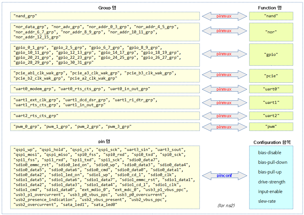
다음 그림에서 pinmux 매핑과 pinconf 매핑 두 가지 상황을 매핑하였다. 좌측에는 핀 또는 그룹명이고 우측은 pinmux 매핑에 사용하는 Function 명과 pinconf 매핑에 사용하는 Configuration 항목이다.


Generic Pin Controller 노드

pin controll 노드는 configuration(pinmux/pinconf) 노드들을 포함할 수 있다. 또한 추가적으로 pin controller 디바이스 드라이버가 초기화 시 Consumer 입장이 되어 pin 들의 초기화를 수행할 수 있다.

  • configuration 노드들은 다음과 같고, 아래에서 설명하는 멀티 스테이트를 사용하는 경우 configuration 노드들은 state 노드들에 포함될 수 있다.
    • pinmux 노드
    • pinconf 노드
    • Mixed pinmux/pinconf 노드
  • 스테이트 별 관리
    • 싱글 스테이트
      • configuration 노드들은 별도의 스테이트 관리를 하지 않고, 클라이언트 디바이스가 한 가지 스테이트만을 사용한다.
    • 멀티 스테이트
      • 클라이언트 디바이스가 두 가지 이상의 스테이트를 런타임에서 요청할 수 있도록 할 수 있다.
  • Consumer 입장
    • 이 노드에서 pinctrl-names 및 pinctrl-0 속성의 사용을 하는 경우이다.


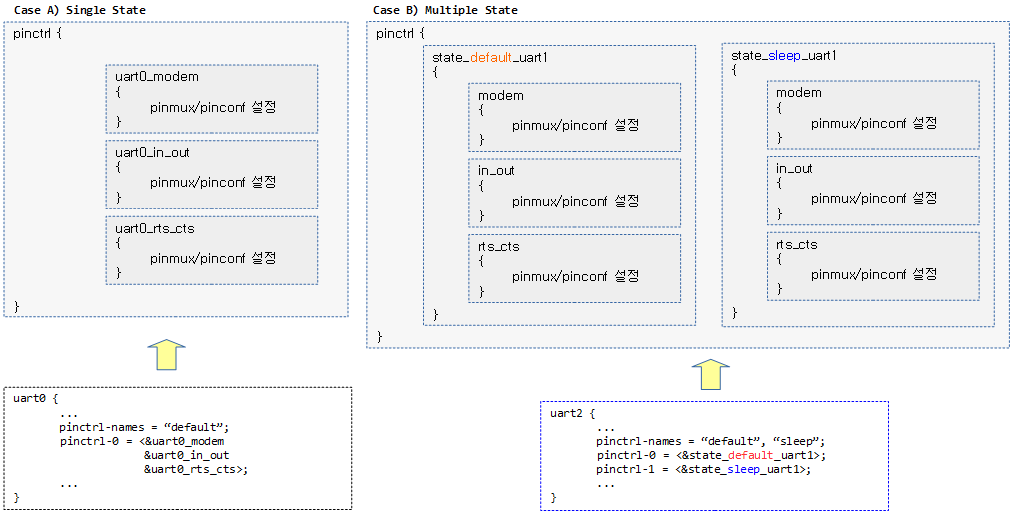
다음 그림은 싱글 또는 멀티 스테이트에 대한 사례이다.


Generic pinmux 노드

아래와 같이 pinmux 노드는 여러 형태로 구성될 수 있다. pinmux 노드 밖에 state를 구분하기 위한 노드로 감쌀 수도 있다.

  • function
    • 선택할 펑션명이다.
  • groups | pins
    • 그룹 리스트 또는 핀 리스트 둘 중 하나가 지정된다.
state_0_node_a {
        uart0 {
                function = "uart0";
                groups = "u0rxtx", "u0rtscts";
        };
};
state_1_node_a {
        spi0 {
                function = "spi0";
                groups = "spi0pins";
        };
};
state_2_node_a { 
        function = "i2c0";
        pins = "mfio29", "mfio30";
};


생성되는 매핑 수
  • pinmux 매핑은 무조건 매핑 대상 수 만큼 만들어진다. pinmux에서 대상은 groups가 될수도 있고 pins가 될 수도 있다.
  • 따라서 위의 코드들의 매핑 수는 순서대로 2개, 1개, 2개이다.


Generic pinconf 노드

아래와 같이 pinconf 노드는 여러 형태로 구성될 수 있다. pinconf 노드 밖에 state를 구분하기 위한 노드로 감쌀 수도 있다.

  • pins | group | pinmux
    • 핀 리스트, 하나의 그룹, 핀먹스 셋 중 하나가 지정된다.
    • 핀 먹스가 사용되는 경우 정수 핀 id 들이 지정된다.
  • 핀에 설정할 항목들
    • bias-pull-down, bias-pull-up, input-enable, …
state_0_node_a {
        cts_rxd {
                pins = "GPIO0_AJ5", "GPIO2_AH4"; /* CTS+RXD */
                bias-pull-up;
        };
};
state_1_node_a {
        rts_txd {
                pins = "GPIO1_AJ3", "GPIO3_AH3"; /* RTS+TXD */
                output-high;
        };
};
state_2_node_a {
        foo {
                group = "foo-group";
                bias-pull-up;
        };
};
state_3_node_a {
        mux {
                pinmux = <GPIOx_PINm_MUXn>, <GPIOx_PINj_MUXk)>;
                input-enable;
        };
};


생성되는 매핑 수
  • pinconf 매핑은 설정 항목의 수와는 무관하고, pinmux와 같이 무조건 매핑 대상 수 만큼 만들어진다.  pinmux에서 대상은 group, pins 또는 pinmux 로 지정된 대상 수 이다.
  • 따라서 위의 코드들의 매핑 수는 순서대로 2개, 2개, 1개, 2개이다.


Mixed pinmux/pinconf 노드

아래와 같이 핀들에 대해 function과 configuraton 항목이 동시에 사용되었음을 알 수 있다. pin controller H/W가 mux를 사용하면서 pin 설정을 동시에 해야 하는 경우가 있다. 이렇게 하나의 노드에서 pinmux와 pinconf 매핑이 동시에 표현되는 경우 커널 내부에서는 하나의 매핑 맵으로 처리하지 않고 pinmux 및 pinconf 매핑 맵을 각각 만들어 관리한다.

arch/arm64/boot/dts/allwinner/sun50i-a64.dtsi

.           mmc0_pins: mmc0-pins {
                pins = "PF0", "PF1", "PF2", "PF3",
                       "PF4", "PF5";
                function = "mmc0";
                drive-strength = <30>;
                bias-pull-up;
            };


생성되는 매핑 수

위의 디바이스 트리 노드 예에서 만들어지는 매핑 수를 알아보자.

  • pins 속성이든 groups 속성이든 해당 속성안에 있는 문자열 수를 매핑에 적용할 대상으로 판단한다.
    •  pins = “PF0”, “PF1”, “PF2”, “PF3”, “PF4”, “PF5″인 경우 대상의 수는 6개이다.
    • groups = “gpio_12_13_grp gpio_14_15_grp”인 경우 핀이 4개일지라도 대상의 수는 2개이다.
  • 위의 코드에서 pinmux 매핑은 무조건 매핑 대상 수 만큼 만들어진다. 따라서 6개이다.
  • 위의 코드에서 pinconf 매핑은 drive-strength 및 bias-pull-up 등의 설정 항목 수와 관계 없이 하나의 매핑에 포함된다. 따라서 6개이다.
  • 총 매핑 수 = 6개 매핑 대상 * (pinmux 1개 + pinconf 1개) = 12개


Consumer로의 사용

pin controller 디바이스 드라이버가 내부에서 Consumer 입장이 되어 pin 설정을 시도할 수도 있다. 이러한 경우 Client 디바이스에서 처럼 pinctrl-names 및 pinctrl-0 속성을 사용할 수 있다. 만일 pin controller가 초기화될 때 pin들의 초기화 설정이 필요 없으면 즉, Consumer 입장이 아니면 아래 두 속성을 지정하지 않아도 된다.

  • pinctrl-names 속성
    • pin 컨트롤러가 제공하는 state 명을 지정한다. state 구분이 필요 없는 경우 보통 “default” 스테이트 명을 사용한다.
    • 만일 N개의 스테이트명을 지정하면 아래 pinctrl-0 부터 pinctrl-N 까지의 속성을 지정해야 한다.
  • pinctrl-0 속성
    • 이 곳에는 phandle 리스트가 입력된다. 각각의 phandle은 pinmux/pinconf 노드를 가리킨다.
	pinctrl: pinctrl {
                ...
		pinctrl-names = "default";
		pinctrl-0 = <&nand_sel &uart3_rx &sdio0_d4>;
                ...
        }

위의 코드에서 pin controller 노드가 pinctrl-names에 “default”하나만 사용되었으므로 싱글 스테이트로만 사용한다. 이러한 경우 pinctrl-0 속성만을 사용한다.


Generic Client 노드

  • pinctrl-names 속성
    • 싱글 스테이트로 사용하는 경우 하나의 스테이트 이름만을 사용한다. 이러한 경우 보통 “default”를 사용한다.
    • 만일 N개의 스테이트명을 지정하면 아래 pinctrl-0 부터 pinctrl-N 까지의 속성을 지정해야 한다.
    • 이 속성은 생략될 수 있으며 그러한 경우 “pinctrl-” 속성 다음에 있는 숫자가 스테이트명이된다.
      • 아래 예에서 두 번째 디바이스의 경우 pinctrl-names = “0”, “1”;으로 지정한 것과 같다.
  • pinctrl-0 ~ pinctrl-N 속성
    • 이 곳에는 phandle 리스트가 입력된다. phandle 각각은 반드시 pin 컨트롤러 노드에 포함된 pinmux/pinconf 노드를 가리켜야 한다.
    • 각 스테이트는 pinctrl-0번부터 시작하여 스테이트 수 만큼 pinctrl-N 까지 순서대로 등록할 수 있다.
    • 이 스테이트 속성값이 블랭크인 경우 state 명에 빈 dummy 매핑만 등록된다.
.       /* For a client device requiring named states */
        device {
                pinctrl-names = "active", "idle";
                pinctrl-0 = <&state_0_node_a>;
                pinctrl-1 = <&state_1_node_a &state_1_node_b>;
        };

        /* For the same device if using state IDs */
        device {
                pinctrl-0 = <&state_0_node_a>;
                pinctrl-1 = <&state_1_node_a &state_1_node_b>;
        };

        /*
         * For an IP block whose binding supports pin configuration,
         * but in use on an SoC that doesn't have any pin control hardware
         */
        device {
                pinctrl-names = "active", "idle";
                pinctrl-0 = <>;
                pinctrl-1 = <>;
        };


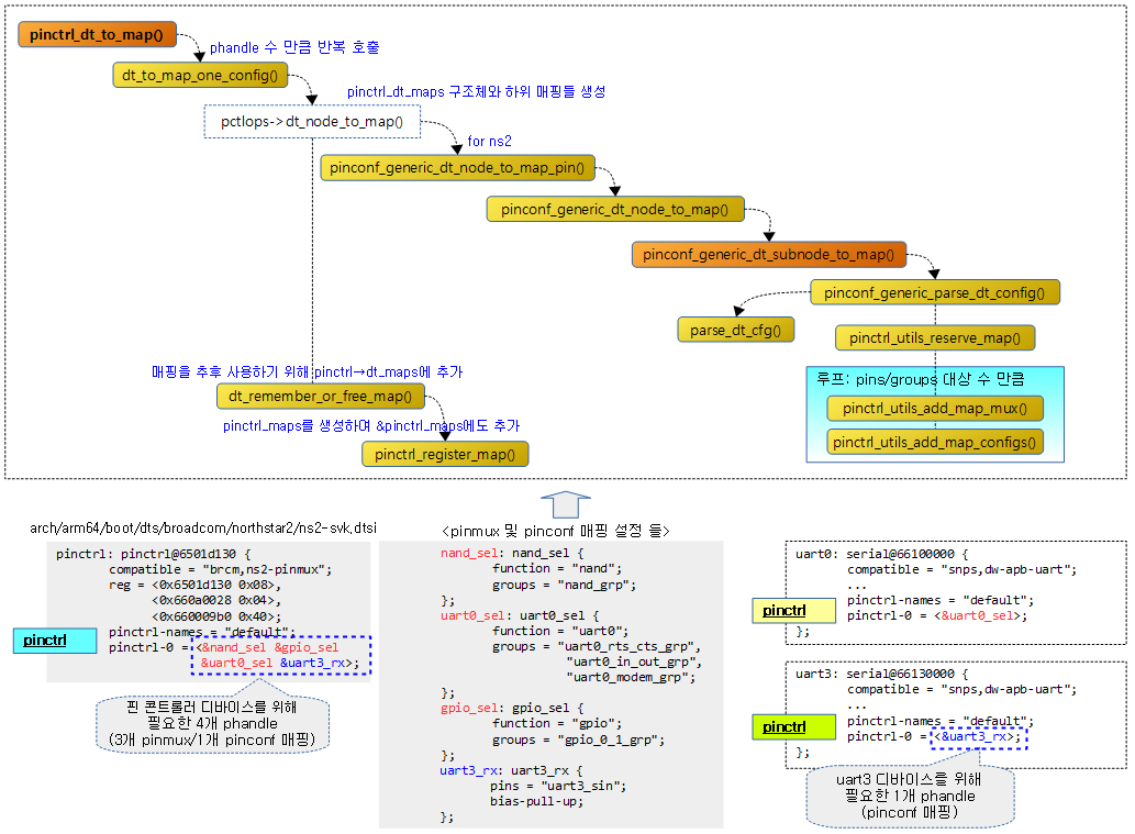
Broadcom ns2 디바이스 트리 사용 예

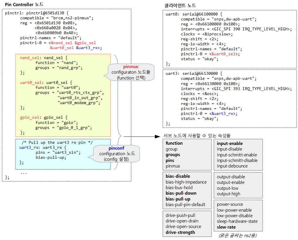
ns2 pin controller H/W는 pinmux를 사용할 수 있는 핀들이 있고, pinconf 를 설정할 수 있는 핀들이 분류되어 있다. 따라서 ns2 pin controller 드라이버는 해당 핀들을 그룹으로 묶어서 매치 시킬 수 있는 항목들이 제한되어 있다. 다음 그림을 보고 좌측에 있는 그룹에 소속한 핀들이 우측 Function 또는 Configuration 항목과 매치 가능한 것을 알 수 있다.


아래 그림에서 사용한 속성과 노드들에 대해 간단히 설명을 하였다.

  • pinctrl-names 속성
    • “default” 스테이트 명 하나만을 사용하였다.
  • pinctrl-0 속성
    • “default” 스테이트 하나만을 사용하였으므로 state id는 0번만을 사용한다. 이 스테이트에는 3개의 pinmux 노드와 1개의 pinconf 노드를 가리키는 phandle을 사용하였다.
  • nand_sel pinmux 노드
    • “nand” 펑션명으로 “nand_grp” 그룹명을 매치시키는 pinmux 매핑이다.
    • 추후 이 pinmux 매핑이 선택되면 “nand_grp”에 속한 많은 핀들이 “nand” 펑션명으로 설정된다.
  • uart0_sel pinmux 노드
    • “uart0” 펑션명으로 3개의 그룹을 매치시키는 pinmux 매핑이다.
    • 추후 이 pinmux 매핑이 선택되면 “uart0_rts_cts_grp” 그룹명에 속한 2개의 핀, “uart0_in_out_grp” 그룹명에 속한 2개의 핀과 “uart0_modem_grp” 그룹명에 속한 4개의 핀들이 “uart0” 펑션으로 설정된다.
  • gpio_sel pinmux 노드
    • “gpio” 펑션명으로 “gpio_0_1_grp” 그룹명을 매치시키는 pinmux 매핑이다.
    • 추후 이 pinmux 매핑이 선택되면 “gpio_0_1_grp” 그룹명에 속한 2개의 핀이 “gpio” 펑션명으로 설정된다.
  • uart3_rx pinconf 노드
    • “uart3_sin” 핀명에 속한 핀을 bias-pull-up 매치시키는 pinconf 매핑이다.
    • 추후 이 pinconf 매핑이 선택되면 “uart3_sin” 핀의 bias를 pull up 시킨다.
  • uart0 클라이언트 노드
    • pinctrl-0 속성
      • 0번 state의 pinmux인 uart0_sel을 통해 3개의 그룹에 속한 핀들을 uart0 펑션으로 변경한다.
  • uart3 클라이언트 노드
    • pinctrl-0 속성
      • 0번 state의 pinconf인 uart3_rx을 통해 uart3_sin 그룹에 속한 핀의 bias를 pull-up으로 설정한다.


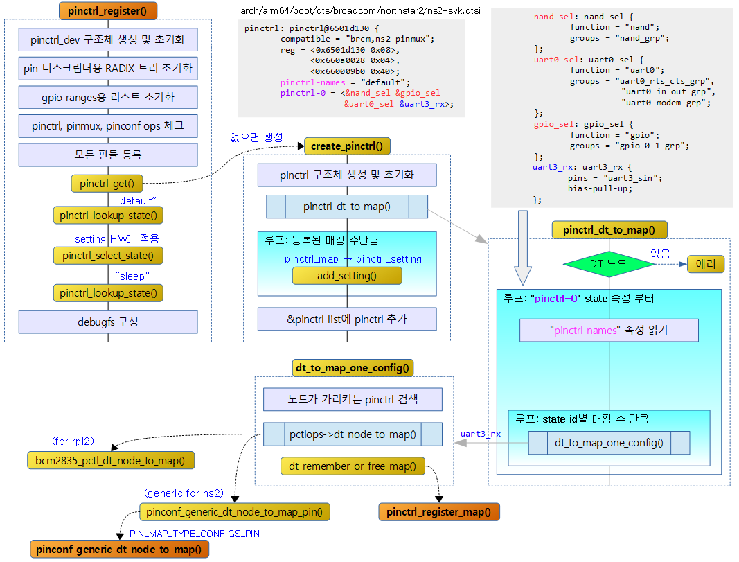
디바이스 트리내에서 핀 컨트롤러 노드와 서브 노드에 정의한 4개의 pinmux/pinconf 노드 및 2 개의 클라이언트 노드를 살펴본다.

arch/arm64/boot/dts/broadcom/northstar2/ns2-svk.dtsi


Pinctrl 생성 및 디바이스 트리로부터 읽어온 매핑 추가

pin controll을 사용하기 위해(Consumer의 입장) pinctrl 구조체를 생성하고 그 밑으로 디바이스 트리 매핑 맵들 및 사용하려는 스테이트들에 해당하는 각 설정들이 관리된다.

  • pinctrl 구조체 아래에 pinctrl_dt_map과 pinctrl_state 두개로 나뉘어 관리하는 모습을 확인하자.
  • 아래 두 개의 그림 사례와 같이 single state로만 관리될 때의 pinctrl_state 구조체의 차이를 확인하자.


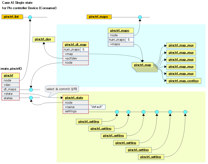
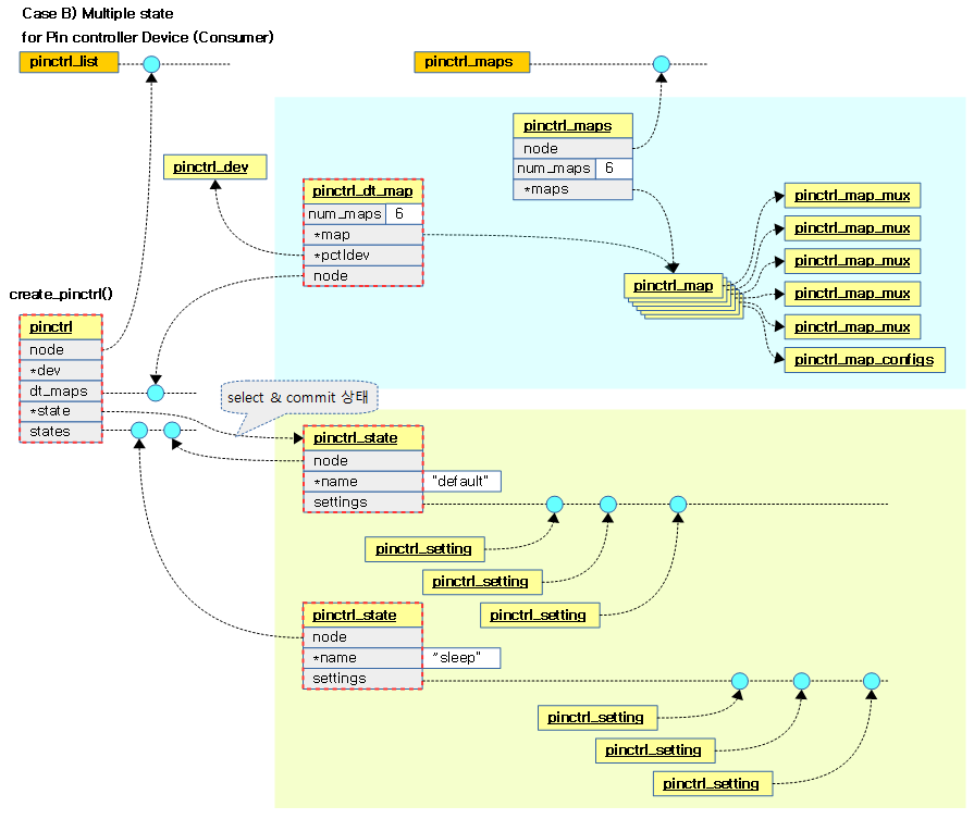
multi state로 관리되는 pinctrl에는 pinctrl_state가 디바이스에서 사용하는 스테이트 수 만큼 복수개가 등록됨을 알 수 있다.


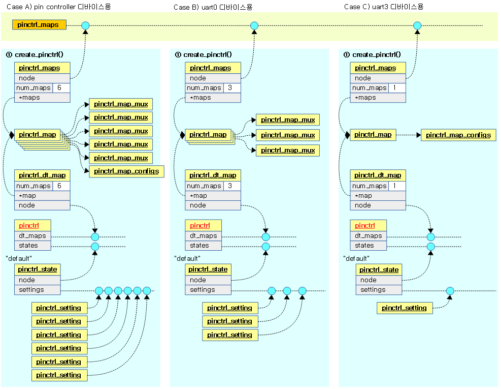
다음 그림은 여러 개의 디바이스 노드로부터 pinctrl을 생성하는 모습을 보여준다. 기본적으로 pin controller 노드도 consumer 입장에서 호출되었고, 나머지 pin control이 필요한 두 개의 클라이언트 디바이스 노드에서 각각 호출되어 사용된 사례이다.


create_pinctrl()

pin control을 사용해야 하는 디바이스 드라이버를 위해 전용 pinctrl을 생성한다.  생성된 pinctrl 구조체 는 크게 다음 두 가지를 관리한다.

  • 디바이스 트리 매핑 맵
    • 디바이스가 요청하는 모든 스테이트에서 요구되는 pinmux/pinconf 노드들을 찾아 파싱한 후 pincmux/pinconf 매핑 맵으로 만들어 등록된다.
  • 스테이트별 설정
    • 디바이스가 요청하는 각각의 스테이트별로 디바이스  트리 매핑 맵으로에서 pinmux/pinconf 설정들이 등록된다.

drivers/pinctrl/core.c – 1/2

static struct pinctrl *create_pinctrl(struct device *dev,
				      struct pinctrl_dev *pctldev)
{
	struct pinctrl *p;
	const char *devname;
	struct pinctrl_maps *maps_node;
	int i;
	const struct pinctrl_map *map;
	int ret;

	/*
	 * create the state cookie holder struct pinctrl for each
	 * mapping, this is what consumers will get when requesting
	 * a pin control handle with pinctrl_get()
	 */
	p = kzalloc(sizeof(*p), GFP_KERNEL);
	if (!p)
		return ERR_PTR(-ENOMEM);
	p->dev = dev;
	INIT_LIST_HEAD(&p->states);
	INIT_LIST_HEAD(&p->dt_maps);

	ret = pinctrl_dt_to_map(p, pctldev);
	if (ret < 0) {
		kfree(p);
		return ERR_PTR(ret);
	}

	devname = dev_name(dev);
  • 코드 라인 16~19에서 첫 번째 인자로 요청한 디바이스를 위해 pinctrl 구조체를 생성하고 pinctrl에서 디바이스를 가리키게 한다.
  • 코드 라인 20~21에서 pinctrl_state 구조체들을 담을 수 있는 리스트와 pinctrl_dt_map을 담을 수 있는 리스트를 초기화한다.
  • 코드 라인 23~27에서 요청 디바이스의 디바이스 트리 노드가 발견된 경우에 한해 pinmux/pinconf 매핑들을 파싱하여 매핑 맵들로 읽어온다.
    • 읽어온 매핑 맵들은 pinctrl_maps와 pinctrl_dt_map 두 구조체에서 관리된다.
  • 코드 라인 29에서 첫 번째 인자로 요청해온 디바이스 이름을 알아온다.
    • 주의: 요청자는 보통 클라이언트 디바이스이지만 핀 컨트롤러 디바이스일 수도 있다.


drivers/pinctrl/core.c – 2/2

	mutex_lock(&pinctrl_maps_mutex);
	/* Iterate over the pin control maps to locate the right ones */
	for_each_maps(maps_node, i, map) {
		/* Map must be for this device */
		if (strcmp(map->dev_name, devname))
			continue;
		/*
		 * If pctldev is not null, we are claiming hog for it,
		 * that means, setting that is served by pctldev by itself.
		 *
		 * Thus we must skip map that is for this device but is served
		 * by other device.
		 */
		if (pctldev &&
		    strcmp(dev_name(pctldev->dev), map->ctrl_dev_name))
			continue;

		ret = add_setting(p, pctldev, map);
		/*
		 * At this point the adding of a setting may:
		 *
		 * - Defer, if the pinctrl device is not yet available
		 * - Fail, if the pinctrl device is not yet available,
		 *   AND the setting is a hog. We cannot defer that, since
		 *   the hog will kick in immediately after the device
		 *   is registered.
		 *
		 * If the error returned was not -EPROBE_DEFER then we
		 * accumulate the errors to see if we end up with
		 * an -EPROBE_DEFER later, as that is the worst case.
		 */
		if (ret == -EPROBE_DEFER) {
			pinctrl_free(p, false);
			mutex_unlock(&pinctrl_maps_mutex);
			return ERR_PTR(ret);
		}
	}
	mutex_unlock(&pinctrl_maps_mutex);

	if (ret < 0) {
		/* If some other error than deferral occurred, return here */
		pinctrl_free(p, false);
		return ERR_PTR(ret);
	}

	kref_init(&p->users);

	/* Add the pinctrl handle to the global list */
	mutex_lock(&pinctrl_list_mutex);
	list_add_tail(&p->node, &pinctrl_list);
	mutex_unlock(&pinctrl_list_mutex);

	return p;
}
  • 코드 라인 3에서 전역 pinctrl_maps 리스트에 등록된 pinctrl_maps 구조체들과 그 멤버 maps가 가리키는 pinctrl_map 구조체 배열을 이중 루프 순회하며 pinctrl_map 구조체를 map 변수에 알아온다.
  • 코드 라인 5~6에서 순회 중인 map의 dev_name이 요청한 디바이스와 다른 경우 skip 한다.
  • 코드 라인 14~16에서 순회 중인 map의 ctrl_dev_name이 pin controller 디바이스 명과 다른 경우도 skip 한다.
  • 코드 라인 18~36에서 매핑 설정을 추가한다. 만일 pin controller 디바이스가 아직 준비되지 않은 경우 pinctrl 이하 모두 할당 해제한다.
  • 코드 라인 40~44에서 기타 이유로 매핑 설정 추가에 실패하는 경우도 pinctrl 이하 모두 할당 해제하고 함수를 빠져나간다.
  • 코드 라인 49~51에서 에러가 없는 경우이다. 생성한 pinctrl을 전역 pinctrl_list에 추가한다.


디바이스 트리로부터 매핑 생성

다음 그림은 클라이언트 디바이스 노드가 요구하는 매핑 맵을 등록할 때의 함수 호출 과정이다.

  • 클라이언트 디바이스 노드로부터 요청
    • “pinctrl-names=”에 요구된 state 명 수만큼 “pinctrl-0” 부터 “pinctrl-N”에 기재된 phandle에 해당하는 노드들
  • Pin controller 디바이스 노드에서 검색
    • phandle이 가리키는 노드가 Pin controller 서브 노드 또는 그 이하 서브 노드에 있는 pinmux/pinconf 노드의 매핑들을 파싱한 후 1개 이상의 매핑 맵을 생성하여 등록한다.


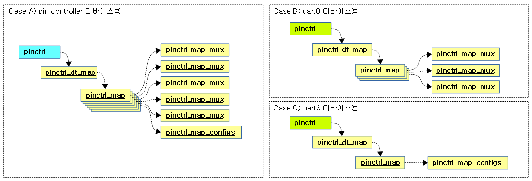
위의 디바이스 트리에서 다음 세 번의 매핑 맵 생성을 요구 받은 경우로 예를 들었다.

  • 첫 번째는 pin controller 디바이스 드라이버로부터 전체 매핑 맵을 만든다.
  • 두 번째 uart0 디바이스 드라이버로부터 pinmux의 펑션 지정을 위해 관련 매핑 맵을 만든다.
  • 세 번째 uart3 디바이스 드라이버로 부터 pinconf 설정을 위해 관련 매핑 맵을 만든다.


pin controller 디바이스측만 더 자세히 자료 구조를 살펴보면 다음과 같다.

  • 6개의 매핑 맵이 구성되어 있음을 알 수 있다.
    • 5개의 pinmux 매핑 맵
    • 1개의 pinconf 매핑 맵
  • 스테이트별로 관리하지 않고 디바이스가 요구하는 매핑들이 pinctrl_dt_map에 한꺼번에 등록되어 관리된다.
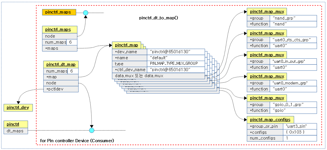
 

pinctrl_dt_to_map()

요청한 디바이스 트리 노드를 읽어 관련 pinmux/pinconf 노드를 파싱한 후 pinctrl_dt_map 구조체 이하에 pinmux/pinconf 매핑 맵을 등록한다.

  • “pinctrl-names” 속성을 통해 스테이트 명을 알아온다.
  • 스테이트명의 개수 만큼 “pinctrl-0” 번 부터 시작하는 “pinctrl-N” 번까지 phandle 리스트를 읽어온다.
  • phandle에 해당하는 pinmux/pinconf  노드를 찾아 해당 설정을 매핑 맵으로 구성한다.
    • pinmux 매핑 맵은 그룹명과 펑션명의 조합이다.
      • 예) uart0_modem_grp에 속한 핀들을 uart0 펑션으로 선택한다.
    • pinconf 매핑 맵은 그룹명 또는 핀명과 설정 항목들의 조합이다. 설정 항목은 복수가 가능하며 설정 값도 포함된다.
      • 예) uart3_pin에 bias-pull-up 설정하고, drive-strength를 30으로 설정한다.

drivers/pinctrl/devicetree.c – 1/2

int pinctrl_dt_to_map(struct pinctrl *p, struct pinctrl_dev *pctldev)
{
	struct device_node *np = p->dev->of_node;
	int state, ret;
	char *propname;
	struct property *prop;
	const char *statename;
	const __be32 *list;
	int size, config;
	phandle phandle;
	struct device_node *np_config;

	/* CONFIG_OF enabled, p->dev not instantiated from DT */
	if (!np) {
		if (of_have_populated_dt())
			dev_dbg(p->dev,
				"no of_node; not parsing pinctrl DT\n");
		return 0;
	}

	/* We may store pointers to property names within the node */
	of_node_get(np);

	/* For each defined state ID */
	for (state = 0; ; state++) {
		/* Retrieve the pinctrl-* property */
		propname = kasprintf(GFP_KERNEL, "pinctrl-%d", state);
		prop = of_find_property(np, propname, &size);
		kfree(propname);
		if (!prop) {
			if (state == 0) {
				of_node_put(np);
				return -ENODEV;
			}
			break;
		}
		list = prop->value;
		size /= sizeof(*list);

		/* Determine whether pinctrl-names property names the state */
		ret = of_property_read_string_index(np, "pinctrl-names",
						    state, &statename);
		/*
		 * If not, statename is just the integer state ID. But rather
		 * than dynamically allocate it and have to free it later,
		 * just point part way into the property name for the string.
		 */
		if (ret < 0) {
			/* strlen("pinctrl-") == 8 */
			statename = prop->name + 8;
		}
  • 코드 라인 14~19에서 디바이스에 해당하는 디바이스 트리 노드가 없는 경우 그냥 함수를 빠져나간다.
  • 코드 라인 25~38에서 “pinctrl-<state>” 속성명을 찾아 phandle 리스트가 담긴 속성 값의 위치는 list에 담고, size에 phandle 개수를 담는다.
    • 예) “pinctrl-0=<&uart0 &uart3>”인 경우 list=uart0 phandle 값, size=2가 담긴다.
  • 코드 라인 41~51에서 “pinctrl-names” 속성명에서 state명을 읽어온다. 만일 발견하지 못한 경우 <state> 문자열로 사용한다.
    • 예) “pinctrl-0″인 경우 statename=”0″이 된다.


drivers/pinctrl/devicetree.c – 2/2

		/* For every referenced pin configuration node in it */
		for (config = 0; config < size; config++) {
			phandle = be32_to_cpup(list++);

			/* Look up the pin configuration node */
			np_config = of_find_node_by_phandle(phandle);
			if (!np_config) {
				dev_err(p->dev,
					"prop %s index %i invalid phandle\n",
					prop->name, config);
				ret = -EINVAL;
				goto err;
			}

			/* Parse the node */
			ret = dt_to_map_one_config(p, pctldev, statename,
						   np_config);
			of_node_put(np_config);
			if (ret < 0)
				goto err;
		}

		/* No entries in DT? Generate a dummy state table entry */
		if (!size) {
			ret = dt_remember_dummy_state(p, statename);
			if (ret < 0)
				goto err;
		}
	}

	return 0;

err:
	pinctrl_dt_free_maps(p);
	return ret;
}
  • 코드 라인 2~13에서 phandle 개수가 담긴 size 수 만큼 루프를 돌며 phandle을 읽어와서 해당 phandle에 해당하는 pinmux/pinconf 설정 노드를 찾아 np_config에 대입한다.
  • 코드 라인 16~21에서 디바이스 트리에서 pinmux/pinconf 설정 노드를 파싱하고 매핑 맵들을 생성한 후 다음 두 개의 자료 구조에 추가하여 관리하게 한다.
    • pinctrl_maps 구조체를 생성하고 파싱한 매핑 맵들을 추가한다.
    • pinctrl_dt_map 구조체를 생성하고 파싱한 매핑 맵들을 추가한다.
  • 코드 라인 24~28에서 phandle이 하나도 없이 비어있는 경우 매핑 맵이 비어있는 dummy용 매핑 맵 하나를 만들어 역시 위의 두개의 자료 구조를 생성하여 그 밑에 추가하여 관리하게 준비한다.
    • pinctrl 구조체 밑으로 자료 구조가 비어 문제가 될 상황을 사전에 없애기 위함이다.
    • 예) “pinctrl-0 = <>;”


하나의 phandle에 대응하는 pinmux/pinconf 노드 파싱 후 매핑 등록

dt_to_map_one_config()

drivers/pinctrl/devicetree.c

static int dt_to_map_one_config(struct pinctrl *p, const char *statename,
                struct device_node *np_config)
{
    struct device_node *np_pctldev;
    struct pinctrl_dev *pctldev;
    const struct pinctrl_ops *ops;
    int ret;
    struct pinctrl_map *map;
    unsigned num_maps;

    /* Find the pin controller containing np_config */
    np_pctldev = of_node_get(np_config);
    for (;;) {
        np_pctldev = of_get_next_parent(np_pctldev);
        if (!np_pctldev || of_node_is_root(np_pctldev)) {
            dev_info(p->dev, "could not find pctldev for node %s, deferring probe\n",
                np_config->full_name);
            of_node_put(np_pctldev);
            /* OK let's just assume this will appear later then */
            return -EPROBE_DEFER;
        }
        pctldev = get_pinctrl_dev_from_of_node(np_pctldev);
        if (pctldev)
            break;
        /* Do not defer probing of hogs (circular loop) */
        if (np_pctldev == p->dev->of_node) {
            of_node_put(np_pctldev);
            return -ENODEV;
        }
    }
    of_node_put(np_pctldev);

    /*
     * Call pinctrl driver to parse device tree node, and
     * generate mapping table entries
     */
    ops = pctldev->desc->pctlops;
    if (!ops->dt_node_to_map) {
        dev_err(p->dev, "pctldev %s doesn't support DT\n",
            dev_name(pctldev->dev));
        return -ENODEV;
    }
    ret = ops->dt_node_to_map(pctldev, np_config, &map, &num_maps);
    if (ret < 0)
        return ret;

    /* Stash the mapping table chunk away for later use */
    return dt_remember_or_free_map(p, statename, pctldev, map, num_maps);
}

하나의 pinmux/pinconf 설정 노드를 파싱하여 매핑 맵들을 생성한다.

  • 코드 라인 12에서 인자로 주어진 pinconf/pinmux 설정 노드가 담긴 np_config를 사용하기 위해 참조 카운터를 1 증가시킨다.
  • 코드 라인 13~29에서 인자로 주어진 pinconf/pinmux 설정 노드의 부모에 pin controller 노드가 있으므로 루프를 돌며 부모 노드 쪽에서 pinctrl 디바이스 노드를 찾는다.  그런 후 찾은 디바이스 노드에 연결된 pinctrl 디바이스를 알아와서 pctldev에 대입한다.
  • 코드 라인 30에서 인자로 주어진 pinconf/pinmux 설정 노드가 담긴 np_config의 사용이 완료되었으므로 참조 카운터를 1 감소시킨다.
  • 코드 라인 37~45에서 pin controller 드라이버에 구현된 ops 후크 함수를 호출하여 pinmux/pinconf 노드를 파싱하여 만든 매핑 맵 수 만큼 pinctrl_map 구조체들을 생성한 후 map 변수명에 담아온다.
    • ns2의 경우 generic 함수인 pinconf_generic_dt_to_map_pin() 함수를 호출한다.
  • 코드 라인 48에서 다음 두 가지 자료 구조에 위에서 파싱하여 만들어진 매핑 맵들을 추후 사용할 수 있도록 등록한다.
    • pinctrl_dt_maps 구조체를 생성한 후 pinctrl->dt_maps에 추가한다.
    • pinctl_maps 구조체를 생성한 후 전역 pinctrl_maps에 추가한다.


Generic pinconf 노드 파싱 및 매핑 등록

pinconf_generic_dt_node_to_map_pin()

include/linux/pinctrl/pinconf-generic.h

static inline int pinconf_generic_dt_node_to_map_pin(
        struct pinctrl_dev *pctldev, struct device_node *np_config,
        struct pinctrl_map **map, unsigned *num_maps)
{
    return pinconf_generic_dt_node_to_map(pctldev, np_config, map, num_maps,
            PIN_MAP_TYPE_CONFIGS_PIN);
}

Generic pinmux/pinconf 노드를 파싱하여 pinmux/pinconf 매핑 맵들을 생성해온다.

  • generic pinconf 노드를 파싱한 경우 대상이 그룹이라하더라도 설정 타입을 pin으로만 사용한다.


pinconf_generic_dt_node_to_map()

drivers/pinctrl/pinconf-generic.c

int pinconf_generic_dt_node_to_map(struct pinctrl_dev *pctldev,
        struct device_node *np_config, struct pinctrl_map **map,
        unsigned *num_maps, enum pinctrl_map_type type)
{
    unsigned reserved_maps;
    struct device_node *np;
    int ret;

    reserved_maps = 0;
    *map = NULL;
    *num_maps = 0;

    ret = pinconf_generic_dt_subnode_to_map(pctldev, np_config, map,
                        &reserved_maps, num_maps, type);
    if (ret < 0)
        goto exit;

    for_each_available_child_of_node(np_config, np) {
        ret = pinconf_generic_dt_subnode_to_map(pctldev, np, map,
                    &reserved_maps, num_maps, type);
        if (ret < 0)
            goto exit;
    }
    return 0;

exit:
    pinctrl_utils_free_map(pctldev, *map, *num_maps);
    return ret;
}
EXPORT_SYMBOL_GPL(pinconf_generic_dt_node_to_map);

generic한 pinmux/pinconf 노드를 파싱하여 pinmux/pinconf 매핑 맵들을 생성해온다. pinconf 노드에서 매핑 맵을 만들 때에는 인자로 전달받은 타입으로 매핑 맵들을 만든다. 타입에 invalid 타입이 주어진 경우 “pin” 속성이 사용된 경우 pin 타입을 사용하고, “groups” 속성을 사용한 경우 group 타입이 지정된다. pinmux 노드인 경우에는 인자로 주어진 타입과 상관 없다.

  • 코드 라인 13~16에서 인자로 전달받은 np_config 디바이스 노드를 파싱하여 매핑 맵들을 만든다.
  • 코드 라인 18~23에서 서브 노드가 있는 경우 이 함수를 재귀호출 처리한다. 이렇게 하는 경우 여러 번의 노드를 파싱하여도 최종으로 하나의 할당에 다 포함되게 하여 반환된다.


pinconf_generic_dt_subnode_to_map()

drivers/pinctrl/pinconf-generic.c -1/2-

int pinconf_generic_dt_subnode_to_map(struct pinctrl_dev *pctldev,
        struct device_node *np, struct pinctrl_map **map,
        unsigned *reserved_maps, unsigned *num_maps,
        enum pinctrl_map_type type)
{
    int ret;
    const char *function;
    struct device *dev = pctldev->dev;
    unsigned long *configs = NULL;
    unsigned num_configs = 0;
    unsigned reserve, strings_count;
    struct property *prop;
    const char *group;
    const char *subnode_target_type = "pins";

    ret = of_property_count_strings(np, "pins");
    if (ret < 0) {
        ret = of_property_count_strings(np, "groups");
        if (ret < 0)
            /* skip this node; may contain config child nodes */
            return 0;
        if (type == PIN_MAP_TYPE_INVALID)
            type = PIN_MAP_TYPE_CONFIGS_GROUP;
        subnode_target_type = "groups";
    } else {
        if (type == PIN_MAP_TYPE_INVALID)
            type = PIN_MAP_TYPE_CONFIGS_PIN;
    }
    strings_count = ret;

    ret = of_property_read_string(np, "function", &function);
    if (ret < 0) {
        /* EINVAL=missing, which is fine since it's optional */
        if (ret != -EINVAL)
            dev_err(dev, "%pOF: could not parse property function\n",
                np);
        function = NULL;
    }

    ret = pinconf_generic_parse_dt_config(np, pctldev, &configs,
                          &num_configs);
    if (ret < 0) {
        dev_err(dev, "%pOF: could not parse node property\n", np);
        return ret;
    }

    reserve = 0;
    if (function != NULL)
        reserve++;
    if (num_configs)
        reserve++;

    reserve *= strings_count;
  • 코드 라인 16~28에서 노드내에 “pins” 속성이 있으면 pin 설정 타입으로 지정한다. 만일 없으면 “groups” 속성을 찾아 group 설정 타입으로 지정한다. 둘 다 없는 경우 child 노드들에서 검색하도록 성공(0) 결과로 함수를 빠져나간다.
  • 코드 라인 29에서 “pins” 또는 “groups” 속성 값에 있는 항목 수를 카운터 한 값이 strings_count에 대입된다.
    • 예) pins = “mfio_13 mfio_14 mfio_15” -> strings_count = 3
  • 코드 라인 31~38에서 “function” 속성 값을 읽어온다. 옵션이므로 없을 수도 있다.
  • 코드 라인 40~45에서 pinconf 설정을 파싱하여 매핑 맵으로 등록한다. 출력 인자 num_configs에는 설정 항목 수가 반환된다.
    • bias-pull-up;  drive-strength = <30>; -> 2개의 설정 항목
  • 코드 라인 47~51에서 매핑 수 만큼 reserve 카운터를 증가시킨다.
    • pinmux 및 pinconf 항목이 둘 다 있으면 reserve 값은 최대 2가 될 수 있다.
  • 코드 라인 53에서 reserve 값에 strings_count를 곱한다.
    • 예) pins = “mfio_13 mfio_14 mfio_15”; function = “uart”;   bias-pull-up;  drive-strength = <30>;
      • 대상이 3개이고 pinmux가 있고, pinconf도 있으므로 -> reserve = 6
      • bias-pull-up 및 drive-strength 등의 설정 항목 수와 상관 없이 pinconf 매핑은 하나만 만들어진다.


drivers/pinctrl/pinconf-generic.c -2/2-

    ret = pinctrl_utils_reserve_map(pctldev, map, reserved_maps,
            num_maps, reserve);
    if (ret < 0)
        goto exit;

    of_property_for_each_string(np, subnode_target_type, prop, group) {
        if (function) {
            ret = pinctrl_utils_add_map_mux(pctldev, map,
                    reserved_maps, num_maps, group,
                    function);
            if (ret < 0)
                goto exit;
        }

        if (num_configs) {
            ret = pinctrl_utils_add_map_configs(pctldev, map,
                    reserved_maps, num_maps, group, configs,
                    num_configs, type);
            if (ret < 0)
                goto exit;
        }
    }
    ret = 0;

exit:
    kfree(configs);
    return ret;
}
EXPORT_SYMBOL_GPL(pinconf_generic_dt_subnode_to_map);
  • 코드 라인 1~4에서 기존 매핑 수가 reserved_maps이고, 새 매핑 수는 num_maps + 위 코드에서 산출한 reserve이다. 새 매핑 수가 기존 매핑 수보다 많은 경우 pinctrl_map 구조체를 새 매핑 수 만큼 다시 생성한다.
  • 코드 라인 6~22에서 “pins” 또는 “groups” 속성에 있는 문자열수 만큼 루프를 돌며 pinmux 매핑이 있는 경우 mux 타입 맵을 추가하고, pinconf 매핑이 있는 경우 pinconf 타입 맵을 추가한다.


pinconf_generic_parse_dt_config()

drivers/pinctrl/pinconf-generic.c

/**
 * pinconf_generic_parse_dt_config()
 * parse the config properties into generic pinconfig values.
 * @np: node containing the pinconfig properties
 * @configs: array with nconfigs entries containing the generic pinconf values
 *           must be freed when no longer necessary.
 * @nconfigs: umber of configurations
 */
int pinconf_generic_parse_dt_config(struct device_node *np,
                    struct pinctrl_dev *pctldev,
                    unsigned long **configs,
                    unsigned int *nconfigs)
{
    unsigned long *cfg;
    unsigned int max_cfg, ncfg = 0;
    int ret;

    if (!np)
        return -EINVAL;

    /* allocate a temporary array big enough to hold one of each option */
    max_cfg = ARRAY_SIZE(dt_params);
    if (pctldev)
        max_cfg += pctldev->desc->num_custom_params;
    cfg = kcalloc(max_cfg, sizeof(*cfg), GFP_KERNEL);
    if (!cfg)
        return -ENOMEM;

    parse_dt_cfg(np, dt_params, ARRAY_SIZE(dt_params), cfg, &ncfg);
    if (pctldev && pctldev->desc->num_custom_params &&
        pctldev->desc->custom_params)
        parse_dt_cfg(np, pctldev->desc->custom_params,
                 pctldev->desc->num_custom_params, cfg, &ncfg);

    ret = 0;

    /* no configs found at all */
    if (ncfg == 0) {
        *configs = NULL;
        *nconfigs = 0;
        goto out;
    }

    /*
     * Now limit the number of configs to the real number of
     * found properties.
     */
    *configs = kmemdup(cfg, ncfg * sizeof(unsigned long), GFP_KERNEL);
    if (!*configs) {
        ret = -ENOMEM;
        goto out;
    }

    *nconfigs = ncfg;

out:
    kfree(cfg);
    return ret;
}

pinconf 노드인 경우 configration 항목들을 파싱하여 그 수 만큼 unsigned long 타입 배열로 반환한다.

  • 코드 라인 22~27에서 필요한 최대 설정 항목 수만큼 임시 배열을 생성한다. 최대 설정 항목 수는 다음 두 항목의 합을 사용한다.
    • generic 디바이스 노드가 지원하는 설정 항목(bias, drive, …) 수
    • 해당 컨트롤러가 지원하는 custom 설정 항목 수
  • 코드 라인 29에서 generic 디바이스 노드가 지원하는 설정 항목들을 대상으로 인자로 전달받은 디바이스 노드를 파싱한다.
  • 코드 라인 30~33에서 해당 컨트롤러가 지원하는 custom 설정 항목들을 대상으로 인자로 전달받은 디바이스 노드를 파싱한다.
  • 코드 라인 38~42에서 검색된 설정 항목이 하나도 없는 경우 성공(0)으로 함수를 빠져나간다.
  • 코드 라인 48~58에서 검색된 설정 항목 수 만큼 기존 배열을 일부 복사하여 unsigned long 배열을 만들어 출력 인자 configs에 대입한다. 또한 출력 인자 nconfigs에도 검색된 설정 항목 수를 대입한다. 그런 후 처음에 임시로 만든 배열은 할당 해제한다.


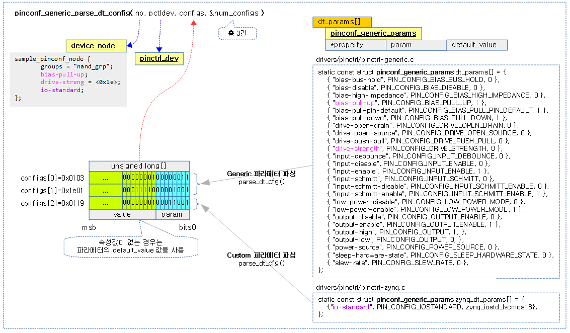
다음 그림은 하나의 pinconf 노드를  파싱하여 출력 인자 configs에 unsigned long 타입 배열로 반환하는 모습을 보여준다.

  • 아래 예에서는 노드안에 3건의 설정을 사용하였다.
  • 파싱 항목을 검색하여 비교할 때 generic 파라메터들과 디바이스 드라이버 벤더에서 제공하는 custom 파라메터들을 대상으로 검색한다.
  • 검색된 항목을 대상으로 unsigned long 타입으로 설정을 만들 때 검색된 속성의 인덱스 번호를 우측 8비트에 사용한다. 그리고 좌측은 파라메터 속성 값이 주어지지 않은 경우에 한하여 파라메터의 멤버 default_value 값을 사용한다.


parse_dt_cfg()

drivers/pinctrl/pinconf-generic.c

/**
 * parse_dt_cfg() - Parse DT pinconf parameters
 * @np: DT node
 * @params: Array of describing generic parameters
 * @count:  Number of entries in @params
 * @cfg:    Array of parsed config options
 * @ncfg:   Number of entries in @cfg
 *
 * Parse the config options described in @params from @np and puts the result
 * in @cfg. @cfg does not need to be empty, entries are added beginning at
 * @ncfg. @ncfg is updated to reflect the number of entries after parsing. @cfg
 * needs to have enough memory allocated to hold all possible entries.
 */
static void parse_dt_cfg(struct device_node *np,
             const struct pinconf_generic_params *params,
             unsigned int count, unsigned long *cfg,
             unsigned int *ncfg)
{
    int i;

    for (i = 0; i < count; i++) {
        u32 val;
        int ret;
        const struct pinconf_generic_params *par = &params[i];

        ret = of_property_read_u32(np, par->property, &val);

        /* property not found */
        if (ret == -EINVAL)
            continue;

        /* use default value, when no value is specified */
        if (ret)
            val = par->default_value;

        pr_debug("found %s with value %u\n", par->property, val);
        cfg[*ncfg] = pinconf_to_config_packed(par->param, val);
        (*ncfg)++;
    }
}

count 수 만큼 루프를 돌며 디바이스 노드에서 속성을 찾아 출력 인자인 cfg 배열에 찾은 속성의 인덱스 번호를 하나씩 채워 넣는다.


pinctrl_utils_reserve_map()

drivers/pinctrl/pinctrl-utils.c

int pinctrl_utils_reserve_map(struct pinctrl_dev *pctldev,
        struct pinctrl_map **map, unsigned *reserved_maps,
        unsigned *num_maps, unsigned reserve)
{
    unsigned old_num = *reserved_maps;
    unsigned new_num = *num_maps + reserve;
    struct pinctrl_map *new_map;

    if (old_num >= new_num)
        return 0;

    new_map = krealloc(*map, sizeof(*new_map) * new_num, GFP_KERNEL);
    if (!new_map) { 
        dev_err(pctldev->dev, "krealloc(map) failed\n");
        return -ENOMEM;
    }

    memset(new_map + old_num, 0, (new_num - old_num) * sizeof(*new_map));

    *map = new_map;
    *reserved_maps = new_num;
    return 0; 
}
EXPORT_SYMBOL_GPL(pinctrl_utils_reserve_map);

필요한 만큼 pinctrl_map 배열을 확장하여 할당한다.

  • 2 단계 이상의 복합 노드로 구성될 때 이 함수가 호출될 때 마다 기존 pinctrl_map 배열보다 점점 커진다. 이 함수에서는 기존 할당된 pinctrl_map 배열을 버리고 더 커진 새 pinctrl_map 배열을 생성하고 기존 데이터를 복제하여 유지한다.


  • 코드 라인 5~10에서 기존 맵 수인 reserved_maps와 새로 만들 num_maps + reserve 와 비교하여 새 맵이 더 크지 않으면 그냥 성공(0) 결과로 새로운 맵 할당 없이 함수를 빠져나간다.
  • 코드 라인 12~16에서 새로 만들어야 하는 맵 수만큼 pinctrl_map 배열을 확장한다.
    • krealloc() 함수를 사용 시 새로 할당한 영역에 기존 기존 데이터는 그대로 복제되어 유지된다.
  • 코드 라인 18~22에서 기존 맵 수보다 추가 생성된 맵 수 만큼 생성한 맵의 뒷 부분을 0으로 클리어한다.


pinctrl_utils_add_map_mux()

drivers/pinctrl/pinctrl-utils.c

int pinctrl_utils_add_map_mux(struct pinctrl_dev *pctldev,
        struct pinctrl_map **map, unsigned *reserved_maps,
        unsigned *num_maps, const char *group,
        const char *function)
{   
    if (WARN_ON(*num_maps == *reserved_maps))
        return -ENOSPC;

    (*map)[*num_maps].type = PIN_MAP_TYPE_MUX_GROUP;
    (*map)[*num_maps].data.mux.group = group;
    (*map)[*num_maps].data.mux.function = function;
    (*num_maps)++;

    return 0;
}   
EXPORT_SYMBOL_GPL(pinctrl_utils_add_map_mux);

pinmux 매핑 맵의 자료 구조를 채운다.


pinctrl_utils_add_map_configs()

drivers/pinctrl/pinctrl-utils.c

int pinctrl_utils_add_map_configs(struct pinctrl_dev *pctldev,
        struct pinctrl_map **map, unsigned *reserved_maps,
        unsigned *num_maps, const char *group,
        unsigned long *configs, unsigned num_configs,
        enum pinctrl_map_type type)
{
    unsigned long *dup_configs;

    if (WARN_ON(*num_maps == *reserved_maps))
        return -ENOSPC;

    dup_configs = kmemdup(configs, num_configs * sizeof(*dup_configs),
                  GFP_KERNEL);
    if (!dup_configs) {
        dev_err(pctldev->dev, "kmemdup(configs) failed\n");
        return -ENOMEM;
    }

    (*map)[*num_maps].type = type;
    (*map)[*num_maps].data.configs.group_or_pin = group;
    (*map)[*num_maps].data.configs.configs = dup_configs;
    (*map)[*num_maps].data.configs.num_configs = num_configs;
    (*num_maps)++;

    return 0;
}
EXPORT_SYMBOL_GPL(pinctrl_utils_add_map_configs);

pinconf 매핑 맵의 자료 구조를 채운다.

  • configs 배열을 복제하여 사용하는 이유는 이 함수를 호출하는 곳에서 원래 configs 배열을 할당 해제한다.


추후 사용하기 위해 디바이스 트리 매핑들 등록

dt_remember_or_free_map()

drivers/pinctrl/devicetree.c

static int dt_remember_or_free_map(struct pinctrl *p, const char *statename,
                   struct pinctrl_dev *pctldev,
                   struct pinctrl_map *map, unsigned num_maps)
{
    int i;
    struct pinctrl_dt_map *dt_map;

    /* Initialize common mapping table entry fields */
    for (i = 0; i < num_maps; i++) {
        map[i].dev_name = dev_name(p->dev);
        map[i].name = statename;
        if (pctldev)
            map[i].ctrl_dev_name = dev_name(pctldev->dev);
    }

    /* Remember the converted mapping table entries */
    dt_map = kzalloc(sizeof(*dt_map), GFP_KERNEL);
    if (!dt_map) {
        dev_err(p->dev, "failed to alloc struct pinctrl_dt_map\n");
        dt_free_map(pctldev, map, num_maps);
        return -ENOMEM;
    }

    dt_map->pctldev = pctldev;
    dt_map->map = map;
    dt_map->num_maps = num_maps;
    list_add_tail(&dt_map->node, &p->dt_maps);

    return pinctrl_register_map(map, num_maps, false);
}

추후 사용하기 위해 파싱되어 알아온 매핑 맵들을 다음 두 위치에 추가한다.

  • pinctrl_dt_map 구조체를 생성한 후 매핑 맵들을 추가한다. 생성한 pinctrl_dt_map은 pinctrl->dt_maps 리스트에 추가하여 관리한다.
  • pinctrl_maps 구조체를 생성한 후 매핑 맵들을 추가한다. 생성한 pinctrl_maps 구조체는 전역 pinctrl_maps 리스트에 추가하여 관리한다.


  • 코드 라인 9~14에서 파싱하여 알아온 매핑 맵들을 그 수만큼 루프를 돌며 디바이스 명과 스테이트 명을 부여한다. pin control 디바이스도 지정된 경우 pin control 디바이스 명도 부여한다.
  • 코드 라인 17~27에서 pinctrl_dt_map 구조체를 만들고 그 밑으로 파싱하여 알아온 매핑맵들을 추가한다.
  • 코드 라인 29에서 pinctrl_maps 구조체를 만들고 그 밑으로 파싱하여 알아온 매핑맵들을 추가한다.
    • 세 번째 인수에 false를 주어 매핑 맵들의 복제는 하지 않는다.


pinctrl_register_map()

이 함수는 pinctrl_maps 구조체를 할당하고 인자로 전달받은 매핑들을 대입한 후 전역 pinctrl_maps 리스트에 추가한다.

drivers/pinctrl/core.c – 1/2

int pinctrl_register_map(const struct pinctrl_map *maps, unsigned num_maps,
			 bool dup)
{
	int i, ret;
	struct pinctrl_maps *maps_node;

	pr_debug("add %u pinctrl maps\n", num_maps);

	/* First sanity check the new mapping */
	for (i = 0; i < num_maps; i++) {
		if (!maps[i].dev_name) {
			pr_err("failed to register map %s (%d): no device given\n",
			       maps[i].name, i);
			return -EINVAL;
		}

		if (!maps[i].name) {
			pr_err("failed to register map %d: no map name given\n",
			       i);
			return -EINVAL;
		}

		if (maps[i].type != PIN_MAP_TYPE_DUMMY_STATE &&
				!maps[i].ctrl_dev_name) {
			pr_err("failed to register map %s (%d): no pin control device given\n",
			       maps[i].name, i);
			return -EINVAL;
		}

		switch (maps[i].type) {
		case PIN_MAP_TYPE_DUMMY_STATE:
			break;
		case PIN_MAP_TYPE_MUX_GROUP:
			ret = pinmux_validate_map(&maps[i], i);
			if (ret < 0)
				return ret;
			break;
		case PIN_MAP_TYPE_CONFIGS_PIN:
		case PIN_MAP_TYPE_CONFIGS_GROUP:
			ret = pinconf_validate_map(&maps[i], i);
			if (ret < 0)
				return ret;
			break;
		default:
			pr_err("failed to register map %s (%d): invalid type given\n",
			       maps[i].name, i);
			return -EINVAL;
		}
	}
  • 코드 라인 10~49에서 인자로 전달받은 maps 배열 수만큼 루프를 돌며 요청 타입에 따른 sanity 체크를 수행한다.


drivers/pinctrl/core.c – 2/2

	maps_node = kzalloc(sizeof(*maps_node), GFP_KERNEL);
	if (!maps_node)
		return -ENOMEM;

	maps_node->num_maps = num_maps;
	if (dup) {
		maps_node->maps = kmemdup(maps, sizeof(*maps) * num_maps,
					  GFP_KERNEL);
		if (!maps_node->maps) {
			kfree(maps_node);
			return -ENOMEM;
		}
	} else {
		maps_node->maps = maps;
	}

	mutex_lock(&pinctrl_maps_mutex);
	list_add_tail(&maps_node->node, &pinctrl_maps);
	mutex_unlock(&pinctrl_maps_mutex);

	return 0;
}
  • 코드 라인 1~15에서 pinctrl_maps 구조체를 할당한 후 인자로 전달받은 매핑 배열인 maps를 가리키게한다. 입력 인자 dup에 따라 매핑 배열을 복제할 수도 있다.
  • 코드 라인 17~19에서 할당받은 pinctrl_maps 구조체를 전역 리스트 pinctrl_maps에 추가한다.


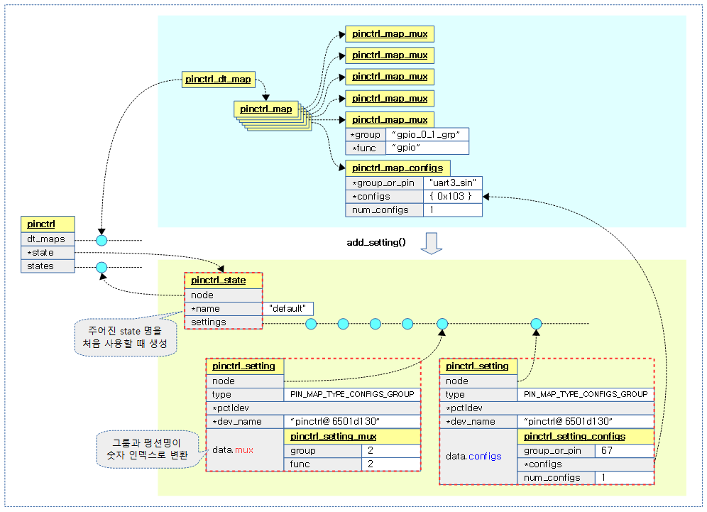
스테이트별 설정(setting) 관리

디바이스 트리로부터 pinmux/pinconf 노드를 파싱하여 관리되고 있는 매핑 맵들을 스테이트 별로 설정들을 관리하도록 준비한다. 아래 그림은 single 스테이트를 사용한 경우이다.

  • pinmux/pinconf 매핑 맵에 있는 문자열을 setting으로 변환할 때 setting에는 인덱스 숫자로 변환되어 사용되도록 한다.
    • “gpio_0_1_grp” 그룹명은 2번 인덱스로 변경
    • “gpio” 펑션명은 2번 인덱스(selector)로 변경
    • “uart3_sin” 핀명은 67번 인덱스로 변경
    • unsigned long으로 표현된 configs 배열은 그대로 변경없이 사용한다.


add_setting()

drivers/pinctrl/core.c

static int add_setting(struct pinctrl *p, struct pinctrl_dev *pctldev,
               const struct pinctrl_map *map)
{
    struct pinctrl_state *state;
    struct pinctrl_setting *setting;
    int ret;

    state = find_state(p, map->name);
    if (!state)
        state = create_state(p, map->name);
    if (IS_ERR(state))
        return PTR_ERR(state);

    if (map->type == PIN_MAP_TYPE_DUMMY_STATE)
        return 0;

    setting = kzalloc(sizeof(*setting), GFP_KERNEL);
    if (!setting)
        return -ENOMEM;

    setting->type = map->type;

    if (pctldev)
        setting->pctldev = pctldev;
    else
        setting->pctldev =
            get_pinctrl_dev_from_devname(map->ctrl_dev_name);
    if (!setting->pctldev) {
        kfree(setting);
        /* Do not defer probing of hogs (circular loop) */
        if (!strcmp(map->ctrl_dev_name, map->dev_name))
            return -ENODEV;
        /*
         * OK let us guess that the driver is not there yet, and
         * let's defer obtaining this pinctrl handle to later...
         */
        dev_info(p->dev, "unknown pinctrl device %s in map entry, deferring probe",
            map->ctrl_dev_name);
        return -EPROBE_DEFER;
    }

    setting->dev_name = map->dev_name;

    switch (map->type) {
    case PIN_MAP_TYPE_MUX_GROUP:
        ret = pinmux_map_to_setting(map, setting);
        break;
    case PIN_MAP_TYPE_CONFIGS_PIN:
    case PIN_MAP_TYPE_CONFIGS_GROUP:
        ret = pinconf_map_to_setting(map, setting);
        break;
    default:
        ret = -EINVAL;
        break;
    }
    if (ret < 0) {
        kfree(setting);
        return ret;
    }

    list_add_tail(&setting->node, &state->settings);

    return 0;
}

인자로 요청한 스테이트명에 해당하는 스테이트 밑으로 pinctrl_state 구조체를 만들고 디바이스 트리 pinmux/pinconf 매핑 맵들을 변환하여 실제 사용하는 인덱스 숫자로 세팅들을 만들어 준비한다.

  • 코드 라인 8~12에서 인자로 주어진 스테이트명으로 스테이트를 검색한 후 처음 사용하는 경우 pinctrl_state 구조체를 생성하고 초기화한다.
  • 코드 라인 14~15에서 dummy 타입 매핑이 발견되면 생략하고 함수를 빠져나간다.
  • 코드 라인 17~42에서 pinctrl_setting 구조체를 할당하고 매핑 맵들의 실제 pinmux/pinconf 매핑 정보를 제외한 일반 정보로 채운다.
  • 코드 라인 44~59에서 pinmux 및 pinconf 매핑 타입에 따라 pinctrl_setting 구조체를 할당하고 매핑 정보에 해당하는 매핑 인덱스 값으로 변환하여 대입한다.
  • 코드 라인 61~63에서 생성한 pinctrl_setting 구조체를 해당 state에 추가하고 성공(0)을 반환한다.


pinmux_map_to_setting()

drivers/pinctrl/pinmux.c

int pinmux_map_to_setting(const struct pinctrl_map *map,
              struct pinctrl_setting *setting)
{
    struct pinctrl_dev *pctldev = setting->pctldev;
    const struct pinmux_ops *pmxops = pctldev->desc->pmxops;
    char const * const *groups;
    unsigned num_groups;
    int ret;
    const char *group;

    if (!pmxops) {
        dev_err(pctldev->dev, "does not support mux function\n");
        return -EINVAL;
    }

    ret = pinmux_func_name_to_selector(pctldev, map->data.mux.function);
    if (ret < 0) {
        dev_err(pctldev->dev, "invalid function %s in map table\n",
            map->data.mux.function);
        return ret;
    }
    setting->data.mux.func = ret;
    
    ret = pmxops->get_function_groups(pctldev, setting->data.mux.func,
                      &groups, &num_groups);
    if (ret < 0) {
        dev_err(pctldev->dev, "can't query groups for function %s\n",
            map->data.mux.function);
        return ret;
    }
    if (!num_groups) {
        dev_err(pctldev->dev,
            "function %s can't be selected on any group\n",
            map->data.mux.function);
        return -EINVAL;
    }
    if (map->data.mux.group) {
        group = map->data.mux.group;
        ret = match_string(groups, num_groups, group);
        if (ret < 0) {
            dev_err(pctldev->dev,
                "invalid group \"%s\" for function \"%s\"\n",
                group, map->data.mux.function);
            return ret;
        }
    } else {
        group = groups[0];
    }

    ret = pinctrl_get_group_selector(pctldev, group);
    if (ret < 0) {
        dev_err(pctldev->dev, "invalid group %s in map table\n",
            map->data.mux.group);
        return ret;
    }
    setting->data.mux.group = ret;

    return 0;
}

pinmux 매핑 맵을 setting으로 변환한다. 매핑 맵이 문자열로 구성되어있는데 이들을  setting에 사용할 인덱스 숫자로 바꾼다.

  • 코드 라인 11~14 pinmux 오퍼레이션이 준비되지 않은 pin controller 디바이스인 경우 pinmux 펑션이 지원되지 않는다는 에러 메시지를 출력하고 함수를 빠져나간다.
  • 코드 라인 16~22에서 function 이름으로 selector 값을 찾아와서 setting의 function 값에 대입한다.
    • ns2 통해 function 명이 “uart0” 인 경우  -> 4
  • 코드 라인 24~36에서 function에서 사용할 수 있는 그룹명들을 groups에 알아온다.
  • 코드 라인 37~45에서 디바이스 트리 pinmux 매핑 맵이 요구하는 그룹명이 위의 groups 배열에서 검색하여 매치되지 않으면 에러를 출력하고 함수를 빠져나간다.
  • 코드 라인 46~48에서 pinmux 매핑 맵에 group 명이 지정되지 않은 경우 pinmux 디바이스 드라이버에서 검색한 그룹의 첫 번째 그룹명을 사용한다.
  • 코드 라인 50~56에서 group명으로 pinmux 디바이스 드라이버가 관리하는 그룹명에서 제공하는group명에 해당하는 selector 인덱스 값을 알아온다.
    • ns2 예) “uart0_modem_grp” 그룹명으로 검색하는 경우 21이 반환된다.


pinmux_func_name_to_selector()

drivers/pinctrl/pinmux.c

static int pinmux_func_name_to_selector(struct pinctrl_dev *pctldev,
                                        const char *function)
{
        const struct pinmux_ops *ops = pctldev->desc->pmxops;
        unsigned nfuncs = ops->get_functions_count(pctldev);
        unsigned selector = 0;

        /* See if this pctldev has this function */
        while (selector < nfuncs) {
                const char *fname = ops->get_function_name(pctldev, selector);

                if (!strcmp(function, fname))
                        return selector;

                selector++;
        }

        dev_err(pctldev->dev, "function '%s' not supported\n", function);
        return -EINVAL;
}

function 이름으로 selector 인덱스 값을 찾아온다.

  • 코드 라인 4~5에서 pin controller 디바이스 드라이버의 pinmux 오퍼레이션에 등록된 (*get_functions_count) 후크 함수를 통해 function의 개수를 알아온다.
    • 예) ns2_get_functions_count() 함수를 사용하여 8을 구해온다.
      • ns2 펑션은 nand, nor, gpio, pcie, uart0, uart1, uart2, pwm 까지 8가지이다.
  • 코드 라인 9~16에서 0번부터 시작하여 함수 개수 만큼 루프를 돌며 디바이스 드라이버의 pinmux 오퍼레이션에 등록된 (*get_function_name)을 통해 함수명을 알아온 function 명과 인자로 요청한 function 명이 일치할 때까지 비교한다. 일치하는 경우 selector 인덱스 값을 반환한다.
    • 예) ns2_get_function_name() 함수를 사용하여 0~7 범위에서 구해온다.


pinconf_map_to_setting()

drivers/pinctrl/pinconf.c

int pinconf_map_to_setting(const struct pinctrl_map *map,
              struct pinctrl_setting *setting)
{   
    struct pinctrl_dev *pctldev = setting->pctldev;
    int pin;
        
    switch (setting->type) {
    case PIN_MAP_TYPE_CONFIGS_PIN:
        pin = pin_get_from_name(pctldev,
                    map->data.configs.group_or_pin);
        if (pin < 0) {
            dev_err(pctldev->dev, "could not map pin config for \"%s\"",
                map->data.configs.group_or_pin);
            return pin;
        }
        setting->data.configs.group_or_pin = pin;
        break;
    case PIN_MAP_TYPE_CONFIGS_GROUP:
        pin = pinctrl_get_group_selector(pctldev,
                     map->data.configs.group_or_pin);
        if (pin < 0) {
            dev_err(pctldev->dev, "could not map group config for \"%s\"",
                map->data.configs.group_or_pin);
            return pin;
        }
        setting->data.configs.group_or_pin = pin;
        break;
    default:
        return -EINVAL;
    }   

    setting->data.configs.num_configs = map->data.configs.num_configs;
    setting->data.configs.configs = map->data.configs.configs;

    return 0;
}

pinconf 매핑 맵을 setting으로 변환한다. 매핑 맵이 문자열로 구성되어있는데 이들을  setting에 사용할 인덱스 숫자로 바꾼다.

  • 코드 라인 7~17에서 pinconf 매핑이 핀 타입인 경우 pin명 에 해당하는 인덱스 값을 알아와서 setting에 대입한다.
    • ns2 통해 function 명이 “uart0_sin” 인 경우  -> 67
  • 코드 라인 18~27에서 pinconf 매핑이 그룹 타입인 경우 group명 에 해당하는 인덱스 값을 알아와서 setting에 대입한다.
  • 코드 라인 32~33에서 pinconf 매핑에 있는 unsigned long 배열 타입의 configs는 그대로 setting에서도 사용한다.


Pin Control 디바이스 드라이버 진입부

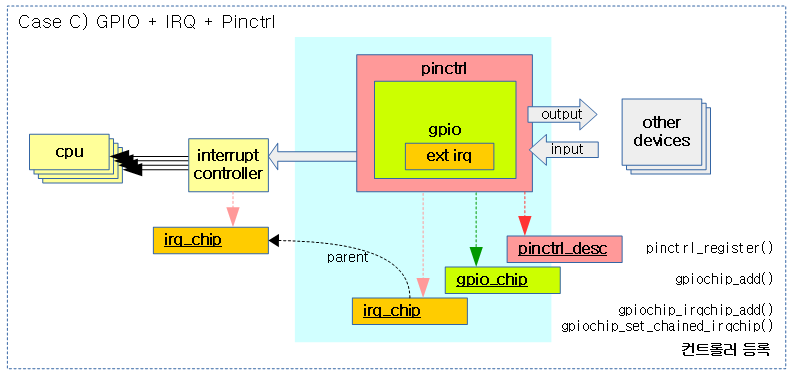
Pin Controller + GPIO controller + interrupt controller 드라이버 등록 – for rpi2

rpi2용 드라이버에는 pin controller 뿐만 아니라 gpio controller와 interrupt controller까지 등록하여 사용하는 코드로 구성되어 있다.

  • rpi2는 gpio 핀을 통해 외부 인터럽트를 수신할 수 있다.

drivers/pinctrl/pinctrl-bcm2835.c

static const struct of_device_id bcm2835_pinctrl_match[] = {
        { .compatible = "brcm,bcm2835-gpio" },
        {}
};
MODULE_DEVICE_TABLE(of, bcm2835_pinctrl_match);

static struct platform_driver bcm2835_pinctrl_driver = {
        .probe = bcm2835_pinctrl_probe,
        .remove = bcm2835_pinctrl_remove,
        .driver = {
                .name = MODULE_NAME,
                .owner = THIS_MODULE,
                .of_match_table = bcm2835_pinctrl_match,
        },
};
module_platform_driver(bcm2835_pinctrl_driver);


bcm2835_pinctrl_probe()

drivers/pinctrl/bcm/pinctrl-bcm2835.c – 1/3

static int bcm2835_pinctrl_probe(struct platform_device *pdev)
{
        struct device *dev = &pdev->dev;
        struct device_node *np = dev->of_node;
        struct bcm2835_pinctrl *pc;
        struct resource iomem;
        int err, i;
        BUILD_BUG_ON(ARRAY_SIZE(bcm2835_gpio_pins) != BCM2835_NUM_GPIOS);
        BUILD_BUG_ON(ARRAY_SIZE(bcm2835_gpio_groups) != BCM2835_NUM_GPIOS);

        pc = devm_kzalloc(dev, sizeof(*pc), GFP_KERNEL);
        if (!pc)
                return -ENOMEM;

        platform_set_drvdata(pdev, pc);
        pc->dev = dev;

        err = of_address_to_resource(np, 0, &iomem);
        if (err) {
                dev_err(dev, "could not get IO memory\n");
                return err;
        }

        pc->base = devm_ioremap_resource(dev, &iomem);
        if (IS_ERR(pc->base))
                return PTR_ERR(pc->base);
  • 코드 라인 11~13에서 bcm2835_pinctrl 구조체를 할당받는다.
  • 코드 라인 15~16에서 인자로 전달받은 플랫폼 디바이스와 bcm2835_pinctrl 구조체와 상호 관계를 연결해둔다.
    • &pdev->dev->driver_data = pc
    • pc->dev = &pdev->dev
  • 코드 라인 18~22에서 디바이스 노드의 ranges 속성에서 읽어들인 IO 주소와 크기를 알아와서 리소스 타입인 iomem에 저장한다.
  • 코드 라인 24~26에서 iomem 리소스 정보로 io 매핑을 한다. 반환되는 결과는 매핑한 가상 주소이다.


drivers/pinctrl/bcm/pinctrl-bcm2835.c – 2/3

.	pc->gpio_chip = bcm2835_gpio_chip;
	pc->gpio_chip.parent = dev;
	pc->gpio_chip.of_node = np;

	for (i = 0; i < BCM2835_NUM_BANKS; i++) {
		unsigned long events;
		unsigned offset;

		/* clear event detection flags */
		bcm2835_gpio_wr(pc, GPREN0 + i * 4, 0);
		bcm2835_gpio_wr(pc, GPFEN0 + i * 4, 0);
		bcm2835_gpio_wr(pc, GPHEN0 + i * 4, 0);
		bcm2835_gpio_wr(pc, GPLEN0 + i * 4, 0);
		bcm2835_gpio_wr(pc, GPAREN0 + i * 4, 0);
		bcm2835_gpio_wr(pc, GPAFEN0 + i * 4, 0);

		/* clear all the events */
		events = bcm2835_gpio_rd(pc, GPEDS0 + i * 4);
		for_each_set_bit(offset, &events, 32)
			bcm2835_gpio_wr(pc, GPEDS0 + i * 4, BIT(offset));

		spin_lock_init(&pc->irq_lock[i]);
	}

	err = gpiochip_add_data(&pc->gpio_chip, pc);
	if (err) {
		dev_err(dev, "could not add GPIO chip\n");
		return err;
	}

	err = gpiochip_irqchip_add(&pc->gpio_chip, &bcm2835_gpio_irq_chip,
				   0, handle_level_irq, IRQ_TYPE_NONE);
	if (err) {
		dev_info(dev, "could not add irqchip\n");
		return err;
	}

위의 코드들은 gpio 컨트롤러를 등록하는 부분들이다. (여기에서는 설명 생략)


drivers/pinctrl/bcm/pinctrl-bcm2835.c – 3/3

	for (i = 0; i < BCM2835_NUM_IRQS; i++) {
		pc->irq[i] = irq_of_parse_and_map(np, i);

		if (pc->irq[i] == 0)
			continue;

		/*
		 * Use the same handler for all groups: this is necessary
		 * since we use one gpiochip to cover all lines - the
		 * irq handler then needs to figure out which group and
		 * bank that was firing the IRQ and look up the per-group
		 * and bank data.
		 */
		gpiochip_set_chained_irqchip(&pc->gpio_chip,
					     &bcm2835_gpio_irq_chip,
					     pc->irq[i],
					     bcm2835_gpio_irq_handler);
	}

	pc->pctl_dev = devm_pinctrl_register(dev, &bcm2835_pinctrl_desc, pc);
	if (IS_ERR(pc->pctl_dev)) {
		gpiochip_remove(&pc->gpio_chip);
		return PTR_ERR(pc->pctl_dev);
	}

	pc->gpio_range = bcm2835_pinctrl_gpio_range;
	pc->gpio_range.base = pc->gpio_chip.base;
	pc->gpio_range.gc = &pc->gpio_chip;
	pinctrl_add_gpio_range(pc->pctl_dev, &pc->gpio_range);

	return 0;
}
  • 코드 라인 1~18에서 이 부분의 코드들은 interrupt controller를 등록하는 부분이다. (여기에서는 설명은 생략)
  • 코드 라인 20~24에서 pinctrl, pinmux 및 pinconf의 오퍼레이션들과 핀 디스크립터들을 포함한 pinctrl 디스크립터 정보로 pin controller를 등록한다.
  • 코드 라인 26~29에서 gpio range를 등록한다. (deprecated)


Pin Control 드라이버 등록 – for ns2

rpi2 드라이버와는 달리 오로지 pin controller 드라이버만으로 구성되어 있다.

drivers/pinctrl/bcm/pinctrl-ns2-mux.c

static const struct of_device_id ns2_pinmux_of_match[] = {
        {.compatible = "brcm,ns2-pinmux"},
        { }
};

static struct platform_driver ns2_pinmux_driver = {
        .driver = {
                .name = "ns2-pinmux",
                .of_match_table = ns2_pinmux_of_match,
        },
        .probe = ns2_pinmux_probe,
};

static int __init ns2_pinmux_init(void)
{
        return platform_driver_register(&ns2_pinmux_driver);
}
arch_initcall(ns2_pinmux_init);


ns2_pinmux_probe()

drivers/pinctrl/bcm/pinctrl-ns2-mux.c

static int ns2_pinmux_probe(struct platform_device *pdev)
{
        struct ns2_pinctrl *pinctrl;
        struct resource *res;
        int i, ret;
        struct pinctrl_pin_desc *pins;
        unsigned int num_pins = ARRAY_SIZE(ns2_pins);

        pinctrl = devm_kzalloc(&pdev->dev, sizeof(*pinctrl), GFP_KERNEL);
        if (!pinctrl)
                return -ENOMEM;

        pinctrl->dev = &pdev->dev; 
        platform_set_drvdata(pdev, pinctrl);
        spin_lock_init(&pinctrl->lock);

        res = platform_get_resource(pdev, IORESOURCE_MEM, 0);
        pinctrl->base0 = devm_ioremap_resource(&pdev->dev, res);
        if (IS_ERR(pinctrl->base0))
                return PTR_ERR(pinctrl->base0);

        res = platform_get_resource(pdev, IORESOURCE_MEM, 1);
        pinctrl->base1 = devm_ioremap_nocache(&pdev->dev, res->start,
                                        resource_size(res));
        if (!pinctrl->base1) {
                dev_err(&pdev->dev, "unable to map I/O space\n");
                return -ENOMEM;
        }

        res = platform_get_resource(pdev, IORESOURCE_MEM, 2);
        pinctrl->pinconf_base = devm_ioremap_resource(&pdev->dev, res);
        if (IS_ERR(pinctrl->pinconf_base))
                return PTR_ERR(pinctrl->pinconf_base);

        ret = ns2_mux_log_init(pinctrl);
        if (ret) {
                dev_err(&pdev->dev, "unable to initialize IOMUX log\n");
                return ret;
        }

        pins = devm_kcalloc(&pdev->dev, num_pins, sizeof(*pins), GFP_KERNEL);
        if (!pins)
                return -ENOMEM;

        for (i = 0; i < num_pins; i++) {
                pins[i].number = ns2_pins[i].pin;
                pins[i].name = ns2_pins[i].name;
                pins[i].drv_data = &ns2_pins[i];
        }

        pinctrl->groups = ns2_pin_groups;
        pinctrl->num_groups = ARRAY_SIZE(ns2_pin_groups);
        pinctrl->functions = ns2_pin_functions;
        pinctrl->num_functions = ARRAY_SIZE(ns2_pin_functions);
        ns2_pinctrl_desc.pins = pins;
        ns2_pinctrl_desc.npins = num_pins;

        pinctrl->pctl = pinctrl_register(&ns2_pinctrl_desc, &pdev->dev,
                        pinctrl);
        if (IS_ERR(pinctrl->pctl)) {
                dev_err(&pdev->dev, "unable to register IOMUX pinctrl\n");
                return PTR_ERR(pinctrl->pctl);
        }
 
        return 0;
}
  • 코드 라인 9~11에서 ns2_pinctrl 구조체를 할당받는다.
  • 코드 라인 13~14에서 인자로 전달받은 플랫폼 디바이스와 bcm2835_pinctrl 구조체와 상호 관계를 연결해둔다.
    • &pdev->dev->driver_data = pc
    • pc->dev = &pdev->dev
  • 코드 라인 17~20에서 플랫폼 디바이스에 저장된 첫 번째 IOMUX 레지스터에 대한 IO 리소스 메모리 정보를 알아온 후 매핑한다. 반환되는 결과는 매핑한 가상 주소이다.
  • 코드 라인 22~28에서 플랫폼 디바이스에 저장된 두 번째 IOMUX 레지스터에 대한 리소스 메모리 정보를 알아온 후 매핑한다. 반환되는 결과는 매핑한 가상 주소이다.
  • 코드 라인 30~33에서 플랫폼 디바이스에 저장된 configuration 레지스터에 대한 리소스 메모리 정보를 알아온 후 매핑한다. 반환되는 결과는 매핑한 가상 주소이다.
  • 코드 라인 35~39에서 최대 NS2_NUM_IOMUX(19)개까지 관리하는 IOMUX 정보를 초기화한다.
  • 코드 라인 41~49에서 pinctrl_pin_desc 구조체를 할당받은 후 컴파일 타임에 구성한 ns2 핀 정보로 대입한다.
  • 코드 라인 51~63에서 pinctrl, pinmux 및 pinconf의 오퍼레이션들과 핀 디스크립터들을 포함한 pinctrl 디스크립터 정보로 pin controller를 등록한다.


Pin Controller 등록

pin controller를 등록하면 디바이스 트리를 통해 부트업 시 pinmux 및 pinconf 매핑 항목들을 동작시킬 수 있다.


pinctrl_register() 함수를 통해 등록되는 pin controller의 관계는 다음과 같다.


pinctrl_register()

이 함수는 pin controller 디바이스를 생성한 후 등록하고 반환한다. 더 자세히 알아보면 다음과 같다.

  • 인자로 전달받은 pinctrl 디스크립터, 디바이스 및 디바이스 데이터를 사용하여 pin controller 디바이스를 생성한다.
  • 내부에서는 pinctrl 디스크립터에서 제공한 pin 디스크립터들을 RADIX 트리에 등록한다.
  • “default” 스테이트를 검색하고 찾은 경우 등록된 pinmux/pinconf 매핑들을 HW에 적용한다.
  • “sleep” 스테이트를 검색하여 알아온다.

drivers/pinctrl/core.c – 1/2

/**
 * pinctrl_register() - register a pin controller device
 * @pctldesc: descriptor for this pin controller
 * @dev: parent device for this pin controller
 * @driver_data: private pin controller data for this pin controller
 */
struct pinctrl_dev *pinctrl_register(struct pinctrl_desc *pctldesc,
                                    struct device *dev, void *driver_data)
{
        struct pinctrl_dev *pctldev;
        int ret;

        if (!pctldesc)
                return ERR_PTR(-EINVAL);
        if (!pctldesc->name)
                return ERR_PTR(-EINVAL);

        pctldev = kzalloc(sizeof(*pctldev), GFP_KERNEL);
        if (pctldev == NULL) {
                dev_err(dev, "failed to alloc struct pinctrl_dev\n");
                return ERR_PTR(-ENOMEM);
        }

        /* Initialize pin control device struct */
        pctldev->owner = pctldesc->owner;
        pctldev->desc = pctldesc;
        pctldev->driver_data = driver_data;
        INIT_RADIX_TREE(&pctldev->pin_desc_tree, GFP_KERNEL);
        INIT_LIST_HEAD(&pctldev->gpio_ranges);
        pctldev->dev = dev;
        mutex_init(&pctldev->mutex);

        /* check core ops for sanity */
        ret = pinctrl_check_ops(pctldev);
        if (ret) {
                dev_err(dev, "pinctrl ops lacks necessary functions\n");
                goto out_err;
        }

        /* If we're implementing pinmuxing, check the ops for sanity */
        if (pctldesc->pmxops) {
                ret = pinmux_check_ops(pctldev);
                if (ret)
                        goto out_err;
        }

        /* If we're implementing pinconfig, check the ops for sanity */
        if (pctldesc->confops) {
                ret = pinconf_check_ops(pctldev);
                if (ret)
                        goto out_err;
        }
  • 코드 라인 18~31에서 pinctrl_dev 구조체를 할당받고 초기화한다.
  • 코드 라인 34~52에서 pinctrl, pinmux, pinconf 오퍼레이션에 대한 sanity 체크를 수행한다.


drivers/pinctrl/core.c – 2/2

        /* Register all the pins */
        dev_dbg(dev, "try to register %d pins ...\n",  pctldesc->npins);
        ret = pinctrl_register_pins(pctldev, pctldesc->pins, pctldesc->npins);
        if (ret) {
                dev_err(dev, "error during pin registration\n");
                pinctrl_free_pindescs(pctldev, pctldesc->pins,
                                      pctldesc->npins);
                goto out_err;
        }

        mutex_lock(&pinctrldev_list_mutex);
        list_add_tail(&pctldev->node, &pinctrldev_list);
        mutex_unlock(&pinctrldev_list_mutex);

        pctldev->p = pinctrl_get(pctldev->dev);

        if (!IS_ERR(pctldev->p)) {
                pctldev->hog_default =
                        pinctrl_lookup_state(pctldev->p, PINCTRL_STATE_DEFAULT);
                if (IS_ERR(pctldev->hog_default)) {
                        dev_dbg(dev, "failed to lookup the default state\n");
                } else {
                        if (pinctrl_select_state(pctldev->p,
                                                pctldev->hog_default))
                                dev_err(dev,
                                        "failed to select default state\n");
                }

                pctldev->hog_sleep =
                        pinctrl_lookup_state(pctldev->p,
                                                    PINCTRL_STATE_SLEEP);
                if (IS_ERR(pctldev->hog_sleep))
                        dev_dbg(dev, "failed to lookup the sleep state\n");
        }

        pinctrl_init_device_debugfs(pctldev);

        return pctldev;

out_err:
        mutex_destroy(&pctldev->mutex);
        kfree(pctldev);
        return ERR_PTR(ret);
}
EXPORT_SYMBOL_GPL(pinctrl_register);
  • 코드 라인 3~9에서 선언된 모든 핀들을 등록시킨다.
  • 코드 라인 11~13에서 전역 리스트 pinctrldev_list에 할당받아 초기화한 pinctrl_dev 구조체를 추가한다.
  • 코드 라인 15에서 디바이스에 대한 pinctrl 구조체를 찾아 얻어온다. pinctrl이 발견되지 않는 경우 create_pinctrl() 함수를 호출하여 pinctrl을 생성해온다.
    • pinctrl을 생성 시에는 pinctrl_dt_to_map() 함수를 호출하여 디바이스 트리를 파싱하여 pinmux/pinconf 매핑 항목들을 pinctrrl_map 구조체에 담아 등록한다. 그런 후 매핑들 수만큼 add_setting() 함수를 호출하여 pinctrl_map을 사용하여 pinctrl_setting 구조체를 생성해내어 등록한다.
  • 코드 라인 17~27에서 pinctrl을 잘 가져온 경우 “default” 상태를 검색하고 찾은 경우 등록된 pinmux/pinconf 매핑들을 HW에 적용한다.
  • 코드 라인 29~33에서 “sleep” 상태를 검색해온다.
  • 코드 라인 36에서 debugfs 용도로 각종 virtual file들을 생성한다.


스테이트 관리

pinctrl_lookup_state()

drivers/pinctrl/core.c

/**
 * pinctrl_lookup_state() - retrieves a state handle from a pinctrl handle
 * @p: the pinctrl handle to retrieve the state from
 * @name: the state name to retrieve
 */
struct pinctrl_state *pinctrl_lookup_state(struct pinctrl *p,
                                                 const char *name)
{
        struct pinctrl_state *state;

        state = find_state(p, name);
        if (!state) {
                if (pinctrl_dummy_state) {
                        /* create dummy state */
                        dev_dbg(p->dev, "using pinctrl dummy state (%s)\n",
                                name);
                        state = create_state(p, name);
                } else
                        state = ERR_PTR(-ENODEV);
        }

        return state;
}
EXPORT_SYMBOL_GPL(pinctrl_lookup_state);

인자로 주어진 pinctrl 구조체와 스테이트 이름으로  pinctrl_state 구조체를 찾아온다.


find_state()

drivers/pinctrl/core.c

static struct pinctrl_state *find_state(struct pinctrl *p,
					const char *name)
{
	struct pinctrl_state *state;

	list_for_each_entry(state, &p->states, node)
		if (!strcmp(state->name, name))
			return state;

	return NULL;
}

인자로 주어진 pinctrl 구조체의 멤버 states 리스트에서 스테이트 이름으로  pinctrl_state 구조체를 찾아온다. 없으면 null을 반환한다.


create_state()

drivers/pinctrl/core.c

static struct pinctrl_state *create_state(struct pinctrl *p,
                                          const char *name)
{
        struct pinctrl_state *state;

        state = kzalloc(sizeof(*state), GFP_KERNEL);
        if (state == NULL) {
                dev_err(p->dev,
                        "failed to alloc struct pinctrl_state\n");
                return ERR_PTR(-ENOMEM);
        }

        state->name = name;
        INIT_LIST_HEAD(&state->settings);

        list_add_tail(&state->node, &p->states);

        return state;
}

pinctrl_state 구조체를 생성한다.

  • 생성한 pinctrl_state 구조체에는 두 번째 인자로 주어진 스테이트 명을 대입한다.
  • 그리고 첫 번째 인자로 받은 pinctrl 구조체에서 멤버 states 리스트에 생성한 구조체를 추가한 후 반환한다.


pinctrl_select_state()

state를 선택하고 pinconf/pinmux setting을 HW에 적용한다. 이미 state가 선택된 경우 무시하고 빠져나온다.

drivers/pinctrl/core.c – 1/2

/**
 * pinctrl_select_state() - select/activate/program a pinctrl state to HW
 * @p: the pinctrl handle for the device that requests configuration
 * @state: the state handle to select/activate/program
 */
int pinctrl_select_state(struct pinctrl *p, struct pinctrl_state *state)
{
	struct pinctrl_setting *setting, *setting2;
	struct pinctrl_state *old_state = p->state;
	int ret;

	if (p->state == state)
		return 0;

	if (p->state) {
		/*
		 * For each pinmux setting in the old state, forget SW's record
		 * of mux owner for that pingroup. Any pingroups which are
		 * still owned by the new state will be re-acquired by the call
		 * to pinmux_enable_setting() in the loop below.
		 */
		list_for_each_entry(setting, &p->state->settings, node) {
			if (setting->type != PIN_MAP_TYPE_MUX_GROUP)
				continue;
			pinmux_disable_setting(setting);
		}
	}

	p->state = NULL;

	/* Apply all the settings for the new state */
	list_for_each_entry(setting, &state->settings, node) {
		switch (setting->type) {
		case PIN_MAP_TYPE_MUX_GROUP:
			ret = pinmux_enable_setting(setting);
			break;
		case PIN_MAP_TYPE_CONFIGS_PIN:
		case PIN_MAP_TYPE_CONFIGS_GROUP:
			ret = pinconf_apply_setting(setting);
			break;
		default:
			ret = -EINVAL;
			break;
		}

		if (ret < 0) {
			goto unapply_new_state;
		}
	}

	p->state = state;

	return 0;
  • 코드 라인 12~13에서 인자로 전달 받은 state가 이미 선택된 경우 아무런 적용 없이 성공리에 함수를 빠져나온다.
  • 코드 라인 15~27에서 기존 state 명으로 적용된 pinmux setting들을 HW에 disable한다.
  • 코드 라인 29에서 임시로 state를 null로 대입한다.
  • 코드 라인 32~49에서 새로운 state 명으로 pinmux/pinconf setting들을 HW에 적용한다.
  • 코드 라인 51~53에서 새 state를 대입하고 성공 결과로 리턴한다.


drivers/pinctrl/core.c – 2/2

unapply_new_state:
	dev_err(p->dev, "Error applying setting, reverse things back\n");

	list_for_each_entry(setting2, &state->settings, node) {
		if (&setting2->node == &setting->node)
			break;
		/*
		 * All we can do here is pinmux_disable_setting.
		 * That means that some pins are muxed differently now
		 * than they were before applying the setting (We can't
		 * "unmux a pin"!), but it's not a big deal since the pins
		 * are free to be muxed by another apply_setting.
		 */
		if (setting2->type == PIN_MAP_TYPE_MUX_GROUP)
			pinmux_disable_setting(setting2);
	}

	/* There's no infinite recursive loop here because p->state is NULL */
	if (old_state)
		pinctrl_select_state(p, old_state);

	return ret;
}
EXPORT_SYMBOL_GPL(pinctrl_select_state);

새 상태를 적용하다 에러가 난 경우 모두 취소한다.


Pinmux HW 설정

pinmux_enable_setting()

pin controller 디바이스 드라이버를 통해 pinmux 설정이 HW에 적용되도록 요청한다.

drivers/pinctrl/pinmux.c

int pinmux_enable_setting(struct pinctrl_setting const *setting)
{
        struct pinctrl_dev *pctldev = setting->pctldev;
        const struct pinctrl_ops *pctlops = pctldev->desc->pctlops;
        const struct pinmux_ops *ops = pctldev->desc->pmxops;
        int ret = 0;
        const unsigned *pins = NULL;
        unsigned num_pins = 0;
        int i;
        struct pin_desc *desc;

        if (pctlops->get_group_pins)
                ret = pctlops->get_group_pins(pctldev, setting->data.mux.group,
                                              &pins, &num_pins);

        if (ret) {
                const char *gname;

                /* errors only affect debug data, so just warn */
                gname = pctlops->get_group_name(pctldev,
                                                setting->data.mux.group);
                dev_warn(pctldev->dev,
                         "could not get pins for group %s\n",
                         gname);
                num_pins = 0;
        }

        /* Try to allocate all pins in this group, one by one */
        for (i = 0; i < num_pins; i++) {
                ret = pin_request(pctldev, pins[i], setting->dev_name, NULL);
                if (ret) {
                        const char *gname;
                        const char *pname;

                        desc = pin_desc_get(pctldev, pins[i]);
                        pname = desc ? desc->name : "non-existing";
                        gname = pctlops->get_group_name(pctldev,
                                                setting->data.mux.group);
                        dev_err(pctldev->dev,
                                "could not request pin %d (%s) from group %s "
                                " on device %s\n",
                                pins[i], pname, gname,
                                pinctrl_dev_get_name(pctldev));
                        goto err_pin_request;
                }
        }
  • 코드 라인 12~14에서 pinmux setting의 group 인덱스에 해당하는 핀들 번로를 알아온다. 알아온 핀들 번호를 pins 변수에, 그리고 핀 개수를 num_pins에 대입한다.
    • ns2의 경우 pin control 디바이스 드라이버의 pinctrl 오퍼레이션에서 (*get_group_pins) 후크 함수를 호출하면 ns2_get_group_pins() 함수를 호출하게 된다.
    • ns2 예) “uart0_modem_grp” 그룹을 의미하는 21번 인덱스가 주어지면 -> pins = {  39, 40, 41, 42 }, num_pins = 4 가 결과로 주어진다.
  • 코드 라인 16~26에서 핀 컨트롤러 드라이버에서 그룹 인덱스로 pin 번호들을 알아오지 못하면 그룹 명을 알아와서 경고 메시지를 출력한다.
    • ns2의 경우 pin control 디바이스 드라이버의 pinctrl 오퍼레이션에서 (*get_group_name) 후크 함수를 호출하면 ns2_get_group_name() 함수를 호출하게 된다.
    • ns2 예) 21번 인덱스가 주어지면 -> gname = “uart0_modem_grp”라는 그룹명이 결과로 주어진다.
  • 코드 라인 29~46에서 그룹에 속한 핀 개수만큼 루프를 돌며 해당 핀의 할당을 하나 하나 시도한다. 만일 요청이 실패하면 에러 메시지를 출력한 후 루프를 도는 도중 할당한 핀을 모두 해제한 후 함수를 빠져나간다.


        /* Now that we have acquired the pins, encode the mux setting */
        for (i = 0; i < num_pins; i++) {
                desc = pin_desc_get(pctldev, pins[i]);
                if (desc == NULL) {
                        dev_warn(pctldev->dev,
                                 "could not get pin desc for pin %d\n",
                                 pins[i]);
                        continue;
                }
                desc->mux_setting = &(setting->data.mux);
        }

        ret = ops->set_mux(pctldev, setting->data.mux.func,
                           setting->data.mux.group);

        if (ret)
                goto err_set_mux;

        return 0;

err_set_mux:
        for (i = 0; i < num_pins; i++) {
                desc = pin_desc_get(pctldev, pins[i]);
                if (desc)
                        desc->mux_setting = NULL;
        }
err_pin_request:
        /* On error release all taken pins */
        while (--i >= 0)
                pin_free(pctldev, pins[i], NULL);

        return ret;
}
  • 코드 라인 2~11에서 그룹에 속한 핀 개수만큼 루프를 돌며 핀 디스크립터를 알아온 후 디스크립터의 mux_setting 값에 pinmux 세팅을 대입한다.
    • desc->mux_setting이 pinctrl_setting_mux 구조체를 가리키게 된다.
  • 코드 라인 13~17에서 group에 속한 핀들에 function을 선택하도록 H/W pin multiplexing을 요청한다.
    • ns2의 경우 pin controller 디바이스 드라이버의 pinmux 오퍼레이션의 (*set_mux) 후크 함수를 호출하면 ns2_pinmux_enable() 함수가 호출된다.


Pinconf HW 설정

pinconf_apply_setting()

drivers/pinctrl/pinconf.c

int pinconf_apply_setting(struct pinctrl_setting const *setting)
{                       
        struct pinctrl_dev *pctldev = setting->pctldev;
        const struct pinconf_ops *ops = pctldev->desc->confops;
        int ret;        
                        
        if (!ops) {
                dev_err(pctldev->dev, "missing confops\n");
                return -EINVAL;
        }

        switch (setting->type) {
        case PIN_MAP_TYPE_CONFIGS_PIN:
                if (!ops->pin_config_set) {
                        dev_err(pctldev->dev, "missing pin_config_set op\n");
                        return -EINVAL;
                }
                ret = ops->pin_config_set(pctldev,
                                setting->data.configs.group_or_pin,
                                setting->data.configs.configs,
                                setting->data.configs.num_configs);
                if (ret < 0) {
                        dev_err(pctldev->dev,
                                "pin_config_set op failed for pin %d\n",
                                setting->data.configs.group_or_pin);
                        return ret;
                }
                break;
        case PIN_MAP_TYPE_CONFIGS_GROUP:
                if (!ops->pin_config_group_set) {
                        dev_err(pctldev->dev,
                                "missing pin_config_group_set op\n");
                        return -EINVAL;
                }
                ret = ops->pin_config_group_set(pctldev,
                                setting->data.configs.group_or_pin,
                                setting->data.configs.configs,
                                setting->data.configs.num_configs);
                if (ret < 0) {
                        dev_err(pctldev->dev,
                                "pin_config_group_set op failed for group %d\n",
                                setting->data.configs.group_or_pin);
                        return ret;
                }
                break;
        default:
                return -EINVAL;
        }

        return 0;
}

pin controller 디바이스 드라이버를 통해 pinconf 설정이 HW에 적용되도록 요청한다.

  • 코드 라인 3~10에서 pin controller 디바이스 드라이버의 pinconf 오퍼레이션이 준비되지 않은 경우 에러 메시지를 출력하고 에러 결과로 함수를 그냥 빠져나간다.
  • 코드라인 12~28에서 핀 인덱스에 해당하는 핀을 찾아 주어진 pinconf setting들을 H/W에 적용하게 한다.
    • ns2의 경우 pin control 디바이스 드라이버의 pinconf 오퍼레이션에서 (*pin_config_set) 후크 함수를 호출하면 ns2_pin_config_set() 함수를 호출하게 된다.
    • ns2 예) “uart3_sin” 핀을 의미하는 67번 인덱스와 0x0103 setting이 주어지면 해당 번호의 핀에 pinconf HW 설정 중 하나인 bias-pull-up 설정이된다.
  • 코드라인 29~45에서 그룹 인덱스에 해당하는 핀들을 대상으로 주어진 pinconf setting들을 H/W에 적용하게 한다.
    • ns2의 경우 pin control 디바이스 드라이버의 pinconf 오퍼레이션에서 (*pin_config_group_set) 후크 함수가 없으므로 에러 메시지가 출력되고 함수를 빠져나간다.
    • 즉, ns2의 경우 그룹을 대상으로 pinconf 설정을 하지 못한다.


디바이스 트리

각 사의 pinctrl 드라이버에서 pin 맵을 코드로 구성하지 않고, 최근에는 대부분 디바이스 트리를 사용하여 pin 맵을 구성하고 있다.

  • 각 사별로 구현이 조금씩 다름에 주의하여야 한다.


arch/arm64/boot/dts/microchip/sparx5.dtsi

                gpio: pinctrl@6110101e0 {
                        compatible = "microchip,sparx5-pinctrl";
                        reg = <0x6 0x110101e0 0x90>, <0x6 0x10508010 0x100>;
                        gpio-controller;
                        #gpio-cells = <2>;
                        gpio-ranges = <&gpio 0 0 64>;
                        interrupt-controller;
                        interrupts = <GIC_SPI 20 IRQ_TYPE_LEVEL_HIGH>;
                        #interrupt-cells = <2>;

                        cs1_pins: cs1-pins {
                                pins = "GPIO_16";
                                function = "si";
                        };

                        cs2_pins: cs2-pins {
                                pins = "GPIO_17";
                                function = "si";
                        };

                        ...


arch/arm64/boot/dts/marvell/cn9132-db.dtsi

        cp2_pinctrl: pinctrl {
                compatible = "marvell,cp115-standalone-pinctrl";

                cp2_i2c0_pins: cp2-i2c-pins-0 {
                        marvell,pins = "mpp37", "mpp38";
                        marvell,function = "i2c0";
                };
                cp2_sdhci_pins: cp2-sdhi-pins-0 {
                        marvell,pins = "mpp56", "mpp57", "mpp58",
                                       "mpp59", "mpp60", "mpp61";
                        marvell,function = "sdio";
                };

                ...


arch/arm64/boot/dts/amlogic/meson-g12-common.dtsi

                                periphs_pinctrl: pinctrl@40 {
                                        compatible = "amlogic,meson-g12a-periphs-pinctrl";
                                        #address-cells = <2>;
                                        #size-cells = <2>;
                                        ranges;

                                        gpio: bank@40 {
                                                reg = <0x0 0x40  0x0 0x4c>,
                                                      <0x0 0xe8  0x0 0x18>,
                                                      <0x0 0x120 0x0 0x18>,
                                                      <0x0 0x2c0 0x0 0x40>,
                                                      <0x0 0x340 0x0 0x1c>;
                                                reg-names = "gpio",
                                                            "pull",
                                                            "pull-enable",
                                                            "mux",
                                                            "ds";
                                                gpio-controller;
                                                #gpio-cells = <2>;
                                                gpio-ranges = <&periphs_pinctrl 0 0 86>;
                                        };

                                        cec_ao_a_h_pins: cec_ao_a_h {
                                                mux {
                                                        groups = "cec_ao_a_h";
                                                        function = "cec_ao_a_h";
                                                        bias-disable;
                                                };
                                        };

                                        ...


arch/arm64/boot/dts/qcom/sdm845.dtsi

                tlmm: pinctrl@3400000 {
                        compatible = "qcom,sdm845-pinctrl";
                        reg = <0 0x03400000 0 0xc00000>;
                        interrupts = <GIC_SPI 208 IRQ_TYPE_LEVEL_HIGH>;
                        gpio-controller;
                        #gpio-cells = <2>;
                        interrupt-controller;
                        #interrupt-cells = <2>;
                        gpio-ranges = <&tlmm 0 0 151>;
                        wakeup-parent = <&pdc_intc>;

                        cci0_default: cci0-default {
                                /* SDA, SCL */
                                pins = "gpio17", "gpio18";
                                function = "cci_i2c";

                                bias-pull-up;
                                drive-strength = <2>; /* 2 mA */
                        };

                        ...


참고